Quote:
Originally Posted by der_wille_zur_macht

Since there are at least a few people with these in-hand or in-construction, I wanted to add a few quick notes about actual use.
First, a photo. Excuse the fact that there are missing components and other "issues" as this was an early prototype I was messing around with. It's also important to note that this is from the first run of boards - the files uploaded have some silkscreen text fixes I'll point out below.
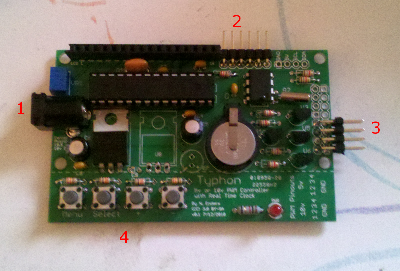
This is the Typhon without the LCD plugged in, so you can see the guts. There are 4 areas of interest with red numbers:
3) The output header. This is a 2-row 90 degree header for connecting your LED drivers. There are actually two 4-pair headers right next to each other, depending on if you're using 5v or 10v outputs. The bottom 4, populated in this photo, are for 10v PWM outputs (i.e. meanwell ELN drivers). The top four, not populated, are for 5v outputs (i.e. buckpucks or most DIY drivers). You only need to populate the four you'll actually be using, no sense wasting headers if you'll never need them. It's VERY IMPORTANT to get polarity correct here, and this is where the silkscreen was corrected. In this 1st-run prototype board, the silk labels - down below the pins on the empty section of board - are BACKWARDS. If you look at the header from the side of the board, the ground pins are the TOP of each pair, and the signal (positive) pins are the BOTTOM of each pair. These are standard .1" male headers I used on this board, so you can use any common square pin .1" female connector - so called "header connectors" or even bits of female headers, or whatever your preference is. These are very common at hobby electronics vendors, and at hobby shops that deal in R/C hobbies, since R/C receivers use .1" connectors, too.
! |
Hi DWZM,
Thanks for the work you have put into this project.
In 3, you noted the following:
50 <-0-5v PWM
50
50
50
10 <-0-10v PWM
10
10
10
are the 1s and 5s in my diagram all grounds?
Do I have the pairs right? I.E. 50 is one pair
Thanks