Now... on to my latest project. With my tank and all its associated equipment in its own room, when my 1/3 hp drop-in coil chiller would come on, all the heat developed by it would be blown directly into this room. A counter-productive situation at best. I'd considered switching to a pass-through or inline chiller but I am not a fan of the plumbing with tank water within running outside in our ultra hot summertime temperatures. So my ideal would be to have my existing chiller unit outside and its chilling coil inside. Sort of the best of both worlds. In order to do this, I needed a housing that would fit around the chiller coil and be water-tight. The coil and its connected hose/line would then be passed through a 4" hole I drilled in the outside wall of the room. There's a rose garden just outside this wall that camouflages and shades the chiller quite well. I will then expanding-foam seal around the hose and fill the hole for insulation. I'll be placing plastic cover plates with holes for the chiller hose and power cord over both sides of this hole to finish it off and protect the insulated hole from weather and for cosmetic reasons inside.
Beings I enjoy working with acrylic, what better material to construct this housing out of. That and I'm a sucker for shiny objects.

I wanted a heavy cast acrylic for strength and when pricing it at my local plastics store, I was offered 1.25" for the price of 1". I guess it's good to be a frequent customer.
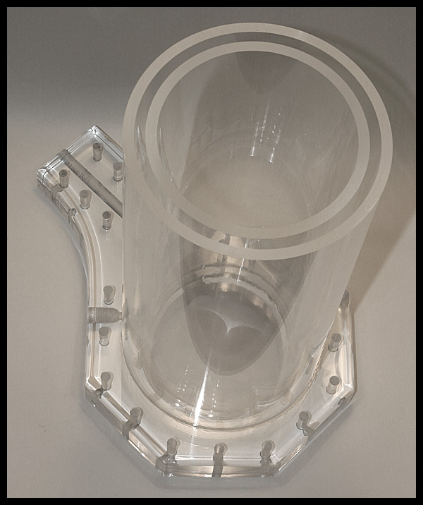
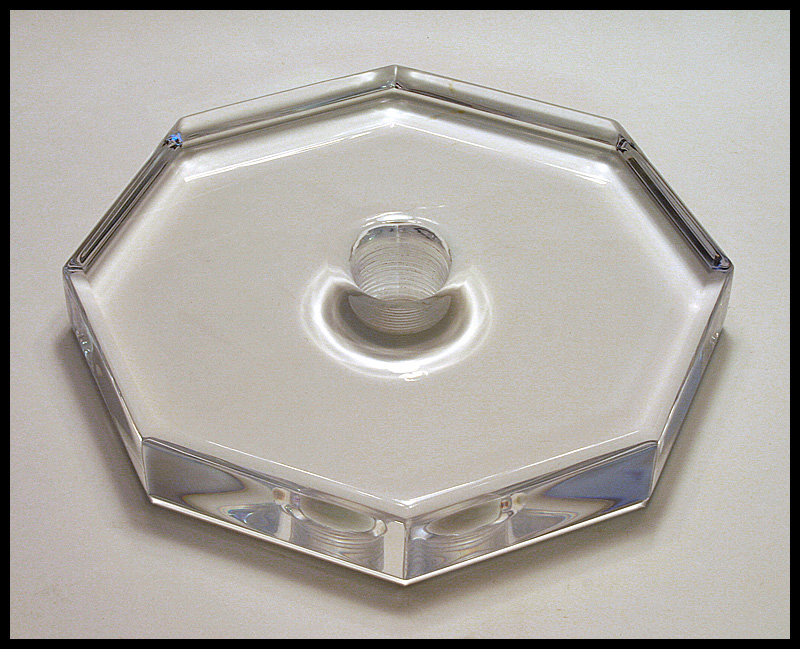
Anyway... the ends would be of this heavy acrylic with one end, the input side, two layers thick which is the flange where the coil enters the housing and makes the water-tight connection. The output end is a single layer. I drilled and threaded a 1" pipe thread hole on both ends for the plumbing to attach. Here's a shot of the output end piece...
Next is a shot of the inlet/flange end. You can see the straight, vertical passage where the coil line exits the housing. This was eventually sealed with O-rings and silicone for good measure.
This shot was prior to cleaning out the bolt holes after drilling them with the rubber flange gasket in place. Basically, the rubber "smeared" inside the holes. Some sandpaper rolled cleaned this out well later.
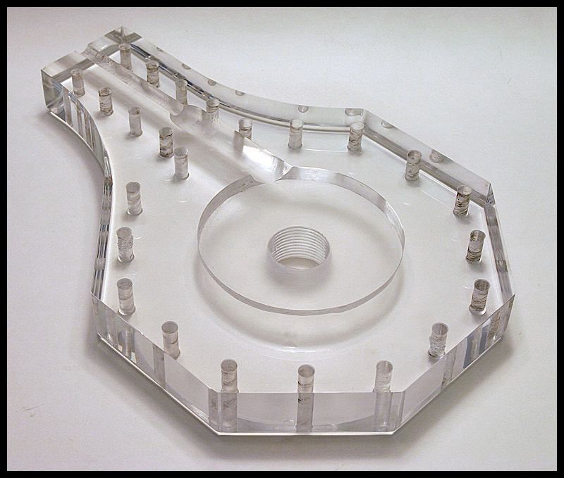
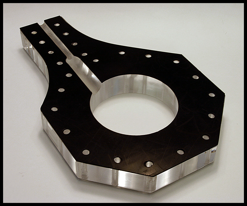
Next up is a shot of the inner portion of the flange that attaches to the cylinders of the housing. The threaded hole at the left I will describe in a bit but this piece mates up to the previous to make up the flange.
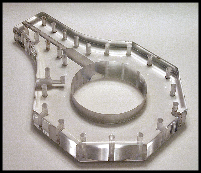
This following shot is simply of the rubber gasket I made to seal between the two halves of the flange.
I also picked up a 5" and a 6", .25" wall cast acrylic tubing. The reason I designed this with two cylinders was so that I could create a vacuum between the two to keep temperature transfer at a minimum. Basically, so the cold remains in the inner chamber and the ambient room temperature outside of the outer cylinder. A little overkill but since I was at it, why not.