
|
|
 07/31/2009, 09:37 AM
|
#1 |
|
Registered Member
Join Date: Feb 2008
Posts: 758
|
Electrical - Did i do this right?
I have to dedicated outlets to my new tank each on their own 20 amp circuit. Each have 3 gfci receptacles in the box. When i test the first one it trips and cuts power to that one and the 2 after it, if i trip the last one then the last one is the only one without power and if i do the middle one then that one and the one after it cuts power...sounds correct from what i understand. Im posting a couple pics just to show how its wired, i used 12-2 wire. I imagine to an electrician from what i have explained and my pictures it should be a piece of cake for someone to verify for me. Here they are:
   Help is greatly appreciated. Thanks Dennis |

|

|
|
07/31/2009, 10:07 AM
|
#2 |
|
Registered Member
Join Date: Jul 2003
Location: Girard, Oh.
Posts: 2,549
|
That'll work but, I'd split each off individuay so one failed device won't trip the whole system.
 I had mine done how you have your setup now and, a failed powerhead set off all of them and caused my tank to crash do to a compleate loss of circulation. Edit: WOW my spelling sucks today!
__________________
-Dave- "Oh ya - I missed one important point. There are other ways to deal with phosphates like phosphate sponges, but it's kind of like trying to fan the stink off a dead skunk." -looser Last edited by dave2184; 07/31/2009 at 10:24 AM. |
|
|
|
|
07/31/2009, 10:16 AM
|
#3 |
|
Registered Member
Join Date: Apr 2009
Location: Victoria, Texas
Posts: 466
|
+1
You have them wired in series so if the first one trips it will take out all of the rest. Wire them parallel so the only receptical that will trip would be the one with the problem. To do this run a power and neutral from each recptical to the home run then tie all the power wires together and all the neutral wires together. |
|
|
|
|
07/31/2009, 10:16 AM
|
#4 |
|
Moved On
Join Date: Oct 2008
Location: here.
Posts: 2,509
|
You can wire them anyway you like but personally I would not want one to trip the other.....on your pig tail you need to splice the hot wire "black" into 3 ind. Wires and run one to each socket this will prevent one gfi from popping the other 2. Same with your nuetral "white" ...the grounds can be jumped from one socket to the next thou.....
|
|
|
|
|
07/31/2009, 11:03 AM
|
#5 | |
|
Registered Member
Join Date: Jul 2004
Location: AWOL
Posts: 12,013
|
Re: Electrical - Did i do this right?
Quote:
I have arbitrarily decided to add this to all GFCI questions: A GFCI will not protect you if you contact both the line (hot) and neutral conductors. A GFCI will not protect you if you contact the output side of a ballast or transformer (since they isolate) Only two examples, the list continues on. Regards, Jim
__________________
"Things should be made as simple as possible, but not simpler." (oft attributed to Einstein; most likely paraphrasing by Roger Sessions; compactly articulates the principle of Occam's Razor) Current Tank Info: 325 6' wide Reef Last edited by uncleof6; 07/31/2009 at 11:16 AM. |
|
|
|
|
|
07/31/2009, 11:05 AM
|
#6 |
|
Registered Member
Join Date: Aug 2008
Location: portland OR
Posts: 162
|
+1 for troy. that's how I would wire it
__________________
Don't force it. Get a bigger hammer! Current Tank Info: 50gal |
|
|
|
|
07/31/2009, 11:47 AM
|
#7 |
|
Registered Member
Join Date: Feb 2003
Location: Pittsburgh
Posts: 20,772
|
How to wire multiple GFCIs to a single branch circuit:
 Now lets talk about what I see in the photos: (please take this as kind advice, as your safety is what is important here). You have used the "stab-ins" on the backs of the receptacles and you have a good bit of bare conductor showing. Never use "stab-ins", they make a very poor connection and are very prone to working lose due to thermal expansion and contraction. ALWAYS use the screw lugs and use them properly. 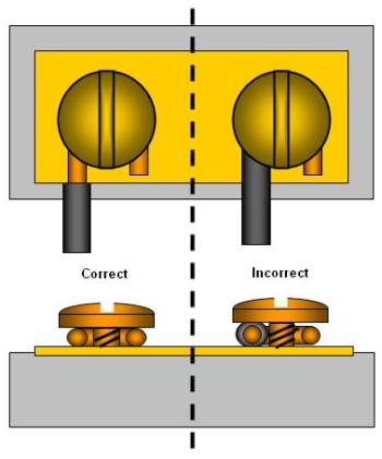 I don't even like the illustration that much, as I prefer to see the conductor wraped tighter around the screw so that it can not fall off even if the screw becomes loose. ALWAYS wrap in the same direction that the screw tightens (clockwise looking at the top of the screw for most devices). |
|
|
|
|
07/31/2009, 11:48 AM
|
#8 | |
|
Registered Member
Join Date: Feb 2003
Location: Pittsburgh
Posts: 20,772
|
Quote:
|
|
|
|
|
|
07/31/2009, 02:06 PM
|
#9 |
|
Registered Member
Join Date: Feb 2008
Posts: 758
|
Im lost....lol
|
|
|
|
|
07/31/2009, 02:18 PM
|
#10 |
|
Moved On
Join Date: Oct 2008
Location: here.
Posts: 2,509
|
just take your home run and split each wire into 3 with a wire nut and 3 short wires......so you have 3 black, 3 white, and 3 green then run a single wire to each gfi......then your done....bean put it out there plain and simple if you cant see it from the digram i would recommend letting someone else wire it for ya....before you get hurt or burn the house down....

|
|
|
|
|
07/31/2009, 02:20 PM
|
#11 |
|
Moved On
Join Date: Oct 2008
Location: here.
Posts: 2,509
|
all you are using on the diagram is the "line "wire as you can see the load is cut off"dont use them"....
|
|
|
|
|
07/31/2009, 02:27 PM
|
#12 | |
|
Registered Member
Join Date: Jul 2004
Location: AWOL
Posts: 12,013
|
Quote:
 Does this help? 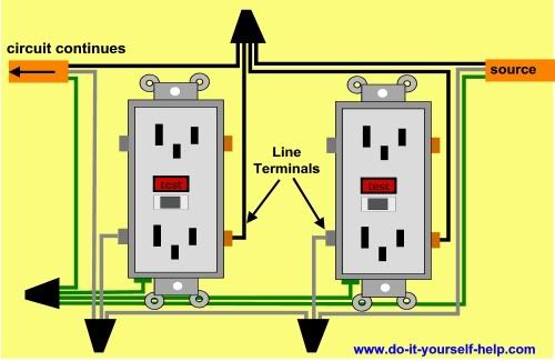 Or if you decide against multiple GFCIs, maybe this will help:  Jim
__________________
"Things should be made as simple as possible, but not simpler." (oft attributed to Einstein; most likely paraphrasing by Roger Sessions; compactly articulates the principle of Occam's Razor) Current Tank Info: 325 6' wide Reef |
|
|
|
|
|
07/31/2009, 03:16 PM
|
#13 |
|
Registered Member
Join Date: Feb 2008
Posts: 758
|
Ive thought about it and asked a few people here at work and i believe i get it now. I want to take the Hot wire and wire nut 2 more lines to feed the other receptacles directly from the original hot wire thats coming in from the braker, same with the neutral, than i can piggy back the grounds as they dont supply power just a means to be grounded so as long as they are all linked and connected to the box im good. Also use the screws and not the plug ins to insure good reliable connection. Sound right?
Thanks |
|
|
|
|
07/31/2009, 03:25 PM
|
#14 | |
|
hmmmmmm
Join Date: Jan 2009
Location: NW Mesa, AZ
Posts: 3,531
|
Quote:
|
|
|
|
|
|
07/31/2009, 03:26 PM
|
#15 |
|
Moved On
Join Date: Oct 2008
Location: here.
Posts: 2,509
|
Yup.....or tie the grounds together like your doing with the others.....
|
|
|
|
|
07/31/2009, 06:29 PM
|
#16 | |
|
Registered Member
Join Date: Feb 2003
Location: Pittsburgh
Posts: 20,772
|
Quote:
|
|
|
|
|
|
07/31/2009, 06:31 PM
|
#17 | |
|
Registered Member
Join Date: Feb 2003
Location: Pittsburgh
Posts: 20,772
|
Quote:
As Uncle mentioned, many people in the know prefer to have the ground lugs orientated to the top. The idea is that if a conductive material (say a metal ruler) were to fall off of a table and slide down the wall, it would hit the ground first instead of shorting accross the hot and neutral conductors. Code (at least to this point) has not made the distinction and the ground lugs may be either up or down and meet code. |
|
|
|
|
|
07/31/2009, 07:18 PM
|
#18 |
|
Registered Member
Join Date: Feb 2008
Posts: 758
|
Thanks for the help and diagrams everyone, im picking up my 250 deep dimension marineland tomorrow and wanted to make sure everything is good b4 i put a tank infront of the receptacles and make fixing the outlets nearly impossible.
Dennis |
|
|
|
 |
| Thread Tools | |
|
|


