
|
|
 05/15/2009, 04:49 PM
|
#1 |
|
Registered Member
Join Date: Feb 2009
Posts: 355
|
Rimless Pico Cube (DIY)
Yes it is rimless cube LOL.
I plan to build a pico reef using acrylics. Since I don't have much experience with pico or nano I need your inputs badly. Below is my planning (see image attached). 1. The pico will be (10"W:10"D:8"H), with internal filtration champers, using 3/8" acrylics and weldon 3 (will be first time trying pin method too). Below is the diagram of the pico. 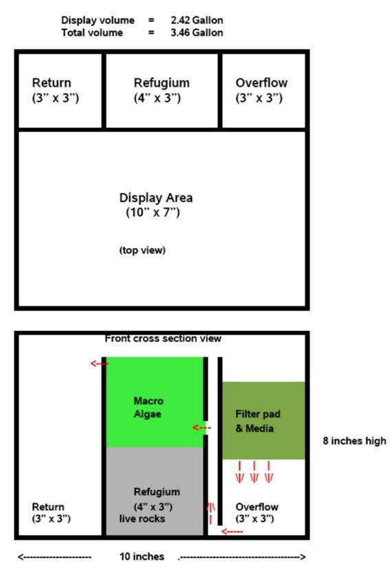 Does my plan make sense? is it good allocated area for each of the compartments? Since I'm not familiar with filtration of nano/pico so not sure if it's something people usually do for nano/pico or not. Also what size of return pump I need for this size of pico? |

|

|
|
05/15/2009, 09:44 PM
|
#2 |
|
Registered Member
Join Date: Jan 2009
Posts: 727
|
It looks good but how high are the teeth or whatever you are using for your overflow? The reason I ask is because you are going to want to make your refuge wall shorter than the bottom of the overflow. Also that gap that lets water into the refuge is usless, all it really does is give a place for water to enter but sence your wall that goes to the return is that high water will also go over the top of the wall that has that gap in it, so really it is pointless. As for a pump, get a really small one.
|
|
|
|
|
05/15/2009, 10:21 PM
|
#3 |
|
Registered Member
Join Date: Jan 2009
Posts: 727
|
|
|
|
|
|
05/15/2009, 11:15 PM
|
#4 |
|
Registered Member
Join Date: Feb 2009
Posts: 355
|
The overflow tees (from display) will be at the highest (~1" down from the top of the tank) then the tees from overflow to fuge will be lower(~3" from the top) and the tees from fuge to return is the second lowest (~2" from the top) so the water when they go through the fuge tend to go up instead of just skimming through the fuge surface.
Looks like my plan is close to what Patriot pointer, so it is not too wrong start. Below is my google sketchup. 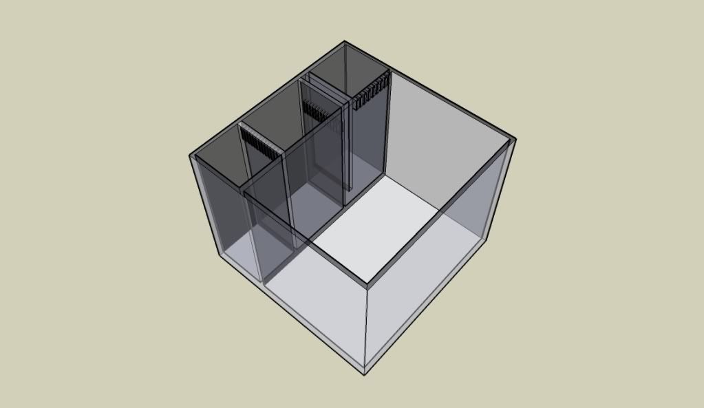 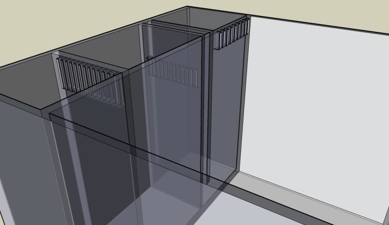 I'm thinking of adding an other bubble trap from fuge to return as I may add a small DIY skimmer (about the size of 16.9oz bottle) in the fuge area. But DIY skimmer is what just came across my mind. About the return pump, it's used as turn over and power head. For the purpose of power head which likely determines how strong the return should be I guess. I got the materials, will update soon. |
|
|
|
|
05/15/2009, 11:43 PM
|
#5 |
|
Registered Member
Join Date: Dec 2008
Location: Gville, FL
Posts: 59
|
The sketch ups look good. Good luck.
|
|
|
|
|
05/15/2009, 11:49 PM
|
#6 |
|
Registered Member
Join Date: May 2008
Location: Cordova,Tn
Posts: 118
|
use the new current usa leds.... I did and it is kinda cool ...
http://reefcentral.com/forums/showth...readid=1628558
__________________
It IS as bad as think and they ARE out to get you..... Current Tank Info: 40 Mixed - 200 gal kush tank |
|
|
|
|
05/16/2009, 07:47 AM
|
#7 |
|
Registered Member
Join Date: Jan 2009
Posts: 727
|
I think you are going to have truble with that wall that goes from the fuge to the return. I think you should move it lower because it is at the same height as your overflow, which means that for it to go over that wall and into your return the water in the overflow area will be just as high and you loose the benifit of surface skimming.
|
|
|
|
|
05/16/2009, 07:54 AM
|
#8 |
|
Registered Member
Join Date: Jun 2007
Location: E. TN.
Posts: 410
|
Looks like a cool project!
|
|
|
|
|
05/16/2009, 10:30 AM
|
#9 |
|
Registered Member
Join Date: Mar 2009
Location: New York
Posts: 154
|
Agree with Patriot54.
designwise, I would ether put two intakes on both sides and one output in the middle or visa-verse. If you put two outputs on both sides it means you use two pumps that can give you enough flow to avoid using any powerheads. |
|
|
|
|
05/16/2009, 10:34 AM
|
#10 |
|
Registered Member
Join Date: Mar 2009
Location: New York
Posts: 154
|
Also for this type of tiny tank you can totally hide everything avoiding cliche designs. Drill it in the bottom (two holes) and then use some good canister filter (eheim) making it use chaeto in the bottom chamber. Check ninjafish or my setup.
|
|
|
|
|
05/16/2009, 03:20 PM
|
#11 |
|
Registered Member
Join Date: Feb 2009
Posts: 355
|
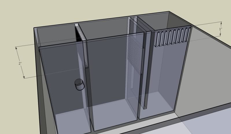
The water from from overflow to the return chamber is gravity moving, I'll add the "slope" between these 2 Tees. The tee from fuge to return will be 1" below the tee of the overflow. Below is the detail sketch. Is 1" slow enough to move about 50Gph of water?
 Acrylics: 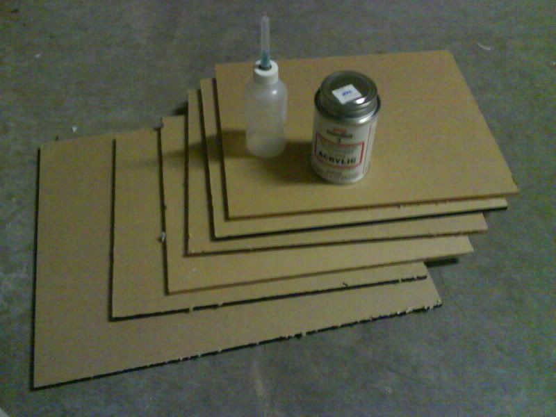 Taping together to visualize the size. 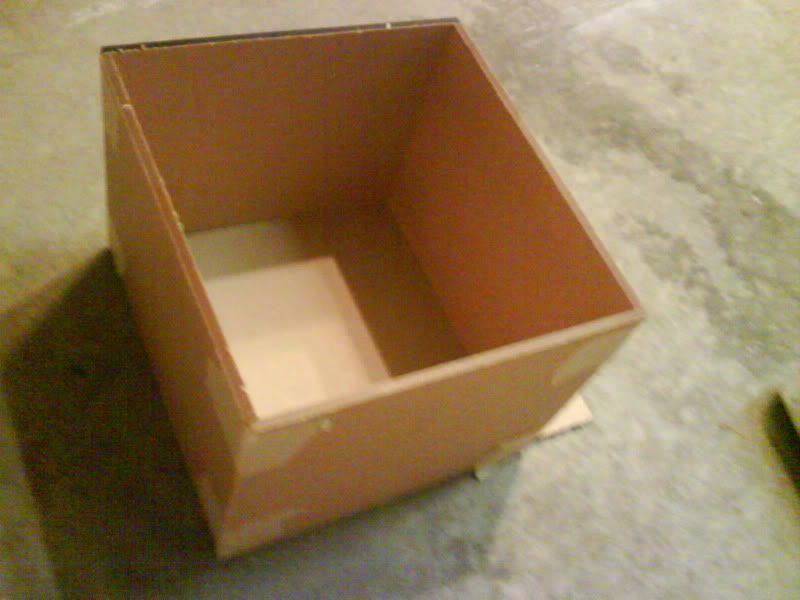 The back panel, bottom panel and all surrounding back filter chambers are black acrylics and front left and right are clear panels. This will be office desktop tank, so the stand will be only about 1" high, and the enclosed canopy will be around 3" high. So I hope to put all equips in the back filter chambers. |
|
|
|
|
05/16/2009, 03:28 PM
|
#12 |
|
Registered Member
Join Date: Feb 2009
Posts: 355
|
Haven't thought much of lighting yet. But probably 2 PC one is 50/50 (white/blue) and one 50/50 (white purple)? light and cooling fans will be a retrofit into a enclosed canopy.
|
|
|
|
|
05/21/2009, 09:26 AM
|
#13 |
|
Registered Member
Join Date: Feb 2009
Posts: 355
|
Not much progress last few days. Have all the pieces cut to fit and all the tee cuts are done.
From right to left: tee from display to the overflow chamber. first tee from overflow chamber to fuge second tee from overflow to fuge tee from fuge to return chamber. 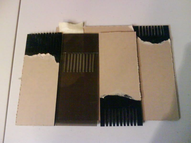
|
|
|
|
|
05/21/2009, 09:29 AM
|
#14 |
|
Registered Member
Join Date: Feb 2009
Posts: 355
|
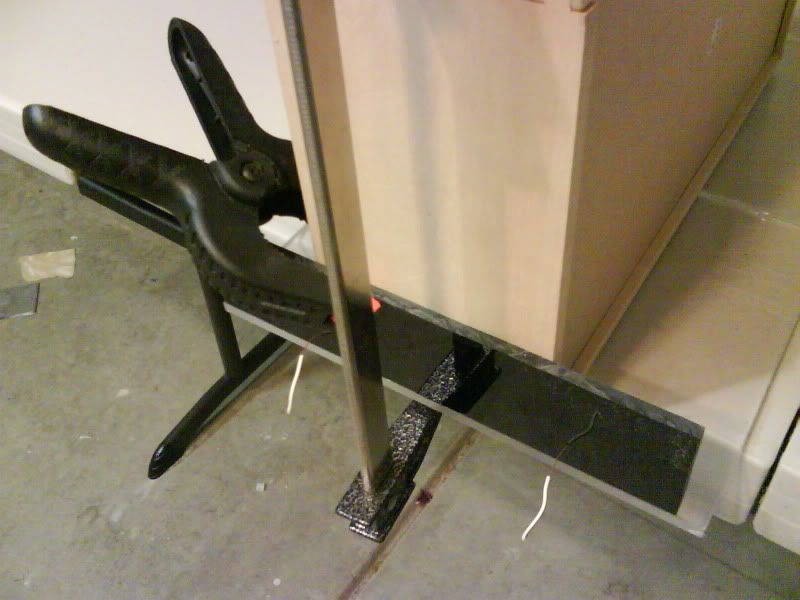
First try on pin method glue but failed. Didn't know how much weldon to put in the join so ended up not enough weldon. Will practice more and probably more..
|
|
|
|
|
05/21/2009, 11:07 AM
|
#15 |
|
Moved On
Join Date: Oct 2008
Location: here.
Posts: 2,509
|
you need to fill the gap between the pieces with solvent untill it becomes clear and no bubbles are present once you have the solvent in place let it set for 30seconds or so before pulling the pins out and push down with minimum force that way you dont squeeze the joint dry.hth. check the diy. forum theres is tons of info and pics on the subject......

|
|
|
|
|
05/21/2009, 11:43 AM
|
#16 |
|
Registered Member
Join Date: Feb 2009
Posts: 355
|
Thanks for the tip. Probably I tried on the black piece so I couldn't see the join clearly, when I first fill the join I saw the solvent ran out to the edge and thought it was too much so I limited the solvent and ended up not enough. I'm going though some acrylic fabrication threads now and will practice a few times more. If I won't be able to get it right then may do it with weldon16. I did my sump baffles with weldon16 and it wasn't too hard.
|
|
|
|
|
05/23/2009, 08:39 AM
|
#17 |
|
Registered Member
Join Date: Feb 2009
Posts: 355
|
I got it done right. The problem was that I put too big space (pin is too big) so the solvent wasn't absorbed by itself and I had to squeeze the bottle to force the solvent in and resulted in not evenly distributed of solvent. With thin space/small pin, the it sucks the solvent in quickly and give nice clear seal. I started to like to work with weldon3 now.
|
|
|
|
|
05/23/2009, 04:05 PM
|
#18 |
|
Moved On
Join Date: Oct 2008
Location: here.
Posts: 2,509
|
sounds like you got it rite.....
i would stay away from 16 if you can it always comes out pretty ugly imo.. lots of bubbles and not nearly as strong as the solvents......if you have any problems just shoot me a pm. i would be happy to help......i live in the diy. forum so i dont really catch the problems in the other forums.....
|
|
|
|
|
05/23/2009, 11:05 PM
|
#19 |
|
Registered Member
Join Date: Feb 2009
Posts: 355
|
Thanks troylee. I'm out of practice and just started on the pico gluing. And yet I made a fish trap out of my practice too. Will post pic later.
|
|
|
|
|
05/24/2009, 11:19 PM
|
#20 |
|
Registered Member
Join Date: Jan 2009
Posts: 727
|
Have any updates?
|
|
|
|
|
05/26/2009, 10:58 AM
|
#21 |
|
Registered Member
Join Date: Feb 2009
Posts: 355
|
Have all pieces glued. Everything looks good. Haven't done water test yet, I will need to do some edge polishing and do water test today. Will post pics later today.
|
|
|
|
|
05/26/2009, 07:46 PM
|
#22 |
|
Registered Member
Join Date: May 2007
Location: Atlanta, GA
Posts: 2,942
|
Can't wait to see more.
|
|
|
|
|
05/26/2009, 09:58 PM
|
#23 |
|
Registered Member
Join Date: Feb 2009
Posts: 355
|
As promised, here are some pics:
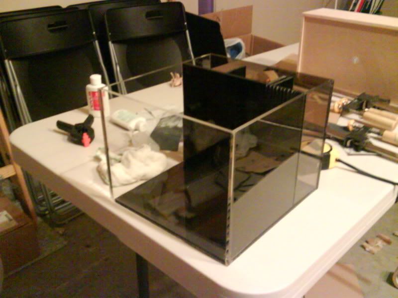 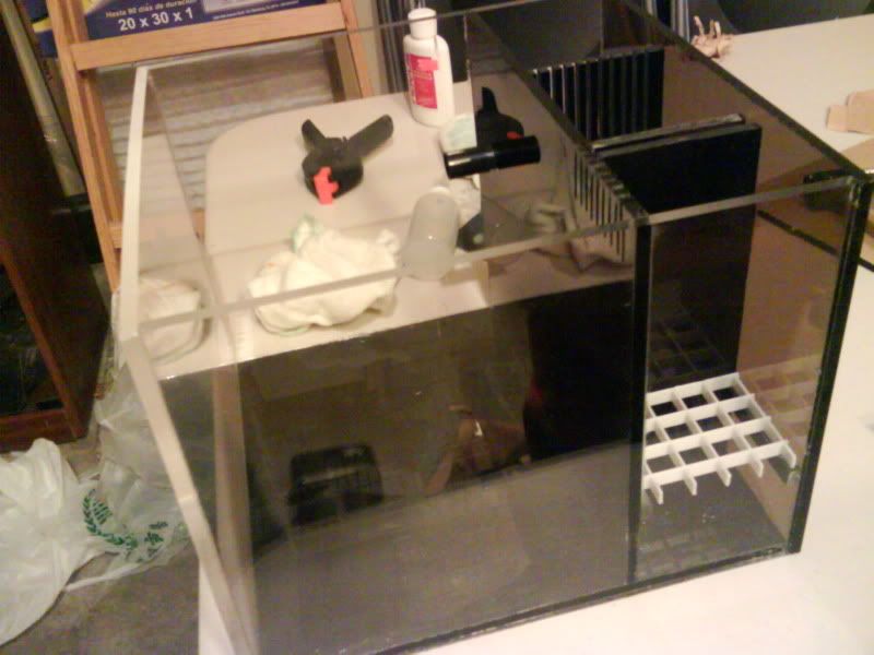 Zoom to seal. A few small bubbles here and there but not much visible and shouldn't cause a leak.(I hope) 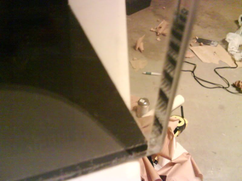 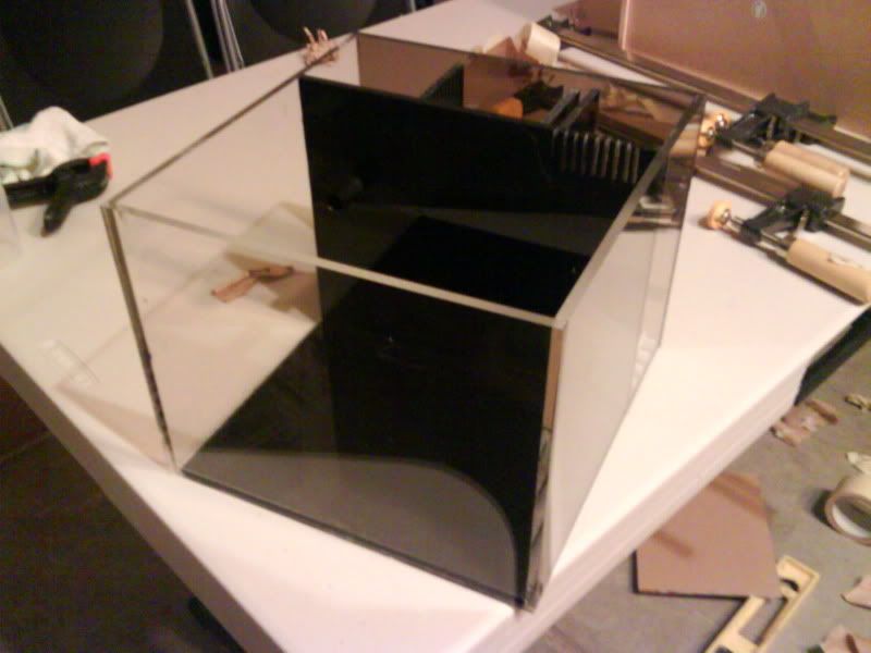 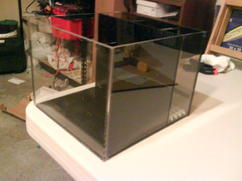 Haven't filled water test yet. Will do soon. Also the stand and canopy builds will be started soon. |
|
|
|
|
05/26/2009, 10:29 PM
|
#24 |
|
Registered Member
Join Date: Feb 2009
Posts: 355
|
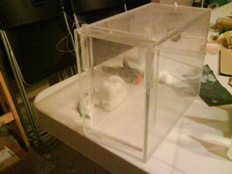
Here is the fish trap that came out from my pin method practice. If anyone locally needs a fish trap to catch fish just PM me :-)
|
|
|
|
|
05/26/2009, 10:33 PM
|
#25 |
|
Registered Member
Join Date: Feb 2009
Posts: 355
|
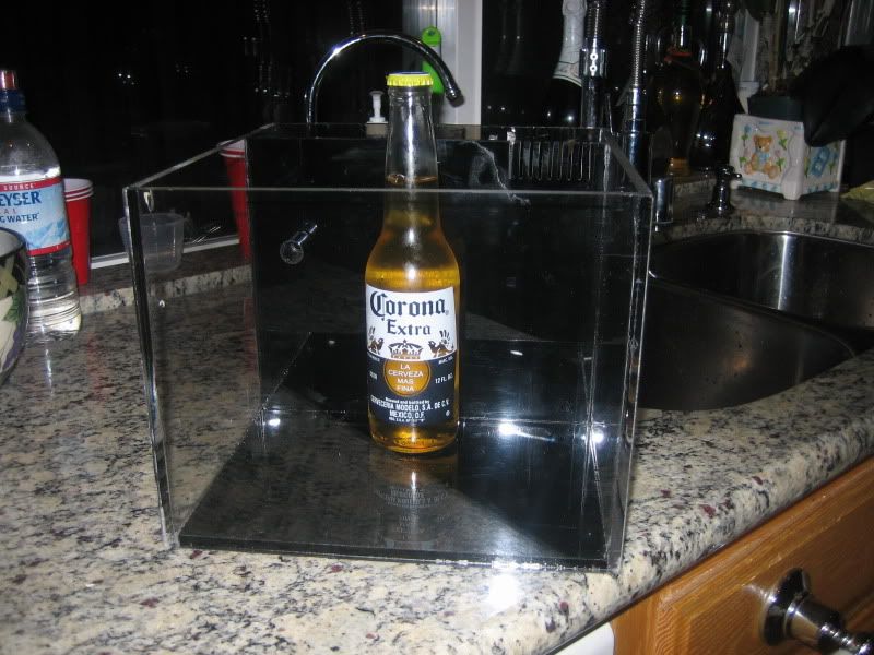
Shown with corona bottle, it's a large pico.
 Will use this to measure water for filling the tank: 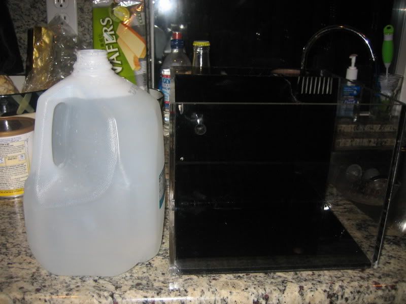
|
|
|
|
 |
|
|


