|
|
 06/22/2011, 04:38 AM
|
#51 |
|
Reef Chemist
 Join Date: Apr 2001
Location: Arlington, Massachusetts
Posts: 86,233
|
I believe it is graphite.

__________________
Randy Holmes-Farley Current Tank Info: 120 mixed reef |

|

|
|
06/22/2011, 07:05 AM
|
#52 | |
|
Registered Member
Join Date: Feb 2003
Location: Pittsburgh
Posts: 20,772
|
Quote:
You act like a planted aquarium hobbyist, and a hydroponics hobbyist, and anything else that will help garner intersest in your "non commerical" kits. You get banned and then move on to the next forum. What is funny is that you think playing these games somehow makes you different than any other spammer who comes here looking to solicit sales for his or her products. Last edited by BeanAnimal; 06/22/2011 at 07:15 AM. |
|
|
|
|
|
06/22/2011, 09:50 AM
|
#53 | |
|
Registered Member
Join Date: Apr 2009
Location: Lithuania
Posts: 396
|
Quote:
|
|
|
|
|
|
06/22/2011, 06:42 PM
|
#54 |
|
Moved On
Join Date: Dec 2010
Posts: 18
|
Excuse me but this thread is about conductivity meter isnt it?and i share my thoughts just like anyone else,no one is pushing you to buy anything. its ok i forgive you BeanAnimal.
|
|
|
|
|
06/22/2011, 06:54 PM
|
#55 | |
|
Moved On
Join Date: Dec 2010
Posts: 18
|
Quote:
cyrusthevirus there is an easier way to generate -12vdc with far less components , i will email you the schematics. |
|
|
|
|
|
06/22/2011, 07:23 PM
|
#56 |
|
Moved On
Join Date: Dec 2010
Posts: 18
|
Dont be hostile BeanAnimal just because someone smarter than you talks about real issues instead of promoting HM products . Because of you i may get banned (no sweat) but you are here to keep folks in your limited narrow circle of products made in Korea.
|
|
|
|
|
06/22/2011, 07:34 PM
|
#57 | |
|
Moved On
Join Date: Dec 2010
Posts: 18
|
Quote:
I am avoiding YOU because youre the only one that acts like an umm how should i say this (OEMTDS fan) that for some reason i dont know what it is ,perhaps youre scared of competition? or lack of knowledge about how conductivity circuitry works , i dont know..whatever it might be ,you try to divert from the real subject and poison the room. |
|
|
|
|
|
08/19/2011, 12:42 AM
|
#58 |
|
Moved On
Join Date: Apr 2011
Location: Colorado
Posts: 246
|
Cyrus,
Any chance of you releasing the eagle and BOM files to the salinity reader? |
|
|
|
|
08/31/2011, 01:51 PM
|
#59 | |
|
Registered Member
Join Date: Jul 2009
Posts: 203
|
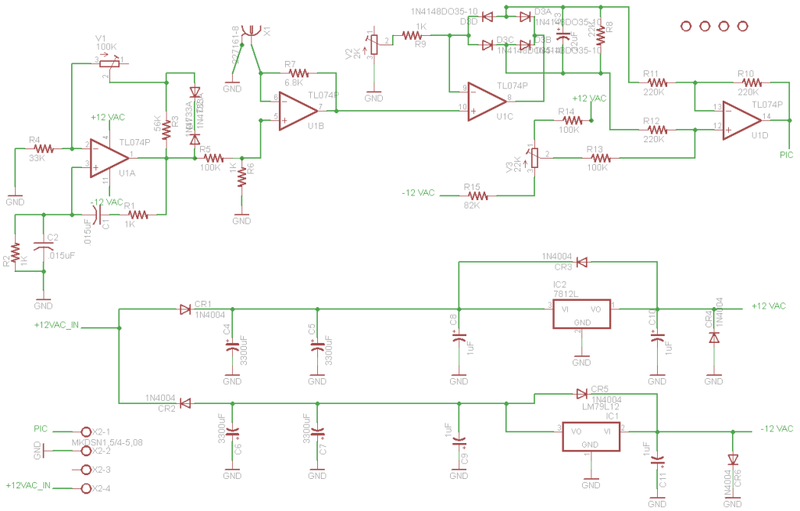
Quote:
BTW I have some extra PCBs of the circuit if you are interested. BOD R1 1K R2 1K R3 56K R4 33K R5 100K R6 1K R7 6.8K R8 22K R9 1K R10 220K R11 220K R12 220K R13 100K R14 100K R15 82K U1 TL074 V1 100K V2 2K V3 22K C1 .015uF C2 .015uF C3 .22uF C4 3300uF C5 3300uF C8 1uF C6 3300uF C7 3300uF C9 1uF C10 1uF C11 1uF D1 1n4733A D2 1n4733A D3A 1N4148DO35-10 D3B 1N4148DO35-10 D3C 1N4148DO35-10 D3D 1N4148DO35-10 CR1 1N4004 CR2 1N4004 CR3 1N4004 CR4 1N4004 CR5 1N4004 CR6 1N4004 IC1 LM79L12 IC2 LM78L12 X1 BNC PCB connector X2 Phoenix CONN TERM BLOCK 4POS 5.08MM PCB X3 DUAL LEAF DIP SOCKETS 14-pins 12VAC 500MA |
|
|
|
|
|
08/31/2011, 01:52 PM
|
#60 |
|
Registered Member
Join Date: Feb 2003
Location: Pittsburgh
Posts: 20,772
|
I think the bigger question is with regard to how the project is working.
|
|
|
|
|
02/08/2012, 09:11 AM
|
#61 |
|
Registered Member
Join Date: Apr 2011
Posts: 38
|
Found this topic from a Google search and thought I'd revive the thread as I'm in the process of building a similar automated system. I'm wondering about the status of this project, and about the probes. I also thought I would add for comment that I've seen elsewhere the use of titanium for the probes. Any thoughts on that?
|
|
|
|
|
08/12/2012, 09:47 AM
|
#62 |
|
Registered Member
Join Date: Aug 2012
Posts: 1
|
....
We're working on a portable water purifier with a built in tester and one of the parameter that our tester should be able to measure is the salinity of water... can you share to us the current status of your circuit? if you could share to us sir... we're also trying to build a ORP tester if there is anything you could share to us we would be very thankful.... poviclang@yahoo.com
Last edited by POPSIE; 08/12/2012 at 09:54 AM. |
|
|
|
|
06/10/2013, 08:40 PM
|
#63 |
|
Registered Member
Join Date: Jul 2009
Posts: 203
|
Every couple of years I get some interest in this circuit so I wanted to provide the current status. Unfortunately the status has not changed. I have EC probes but I am not sure if they will work for the range required. If anyone wants to try to take this project on, PM me. I can send over the prototypes I created. I just don't have the equipment or the time.
|
|
|
|
|
02/08/2014, 08:01 AM
|
#64 |
|
Registered Member
Join Date: Feb 2014
Posts: 1
|
Hi
I am designing a conductivity probe which consists of coaxial cylindrical electrodes in order to measure the electrical conductivity of electrolyte solutions. I can't seem to find any literature on how to go about the design and how these type of sensors work. Do you guys recommend any textbooks or literature that explains this really well as I don't have an electrical background. Many Thanks |
|
|
|
|
10/18/2014, 07:37 AM
|
#65 |
|
Registered Member
Join Date: Oct 2014
Posts: 1
|
TDS Schematic
I used the schematic available at octiva.com but it didn't worked for me. there was no change at output when the water or a connected resistance value was changed.
Please suggest any corrections in that schematic or any other working circuit. Thanks.. |
|
|
|
|
10/18/2014, 08:34 AM
|
#66 |
|
Registered Member
Join Date: Aug 2012
Location: East Meadow, NY
Posts: 33
|
Just skimmed this thread and saw no mention of this company so i figured i'd chime in with it. www.atlas-scientific.com sells all sorts of useful diy probes and circuit boards to read the probes and output i2c or UART. Not exactly cyrusthevirus level DIY but for all the wannabe EE's out there (like me) it should suffice. HTH
|
|
|
|
|
11/26/2014, 03:17 AM
|
#67 | |
|
Registered Member
Join Date: Nov 2014
Posts: 2
|
Quote:
|
|
|
|
|
|
01/03/2015, 11:12 AM
|
#68 |
|
Registered Member
Join Date: Nov 2014
Location: Pennsylvania
Posts: 10
|
Hello All,
I was wondering on how you were making out with your DIY circuit. I was unable to find a completely implemented and tested EC probe and circuit in the Arduino community so I opted to go with this:
The Atlas Scientific stuff is expensive but easy to interface with and accurate. It expects you to know your probes cell constant (K) value. This is apparently related to the distance between conductors and the surface area exposed. I have yet to see a cheap probe specify this value. I have reached out to several vendors and am awaiting a response. I have both 111800us/cm and 12880us/cm conductivity solution to perform a two-point (high/low) calibration. After calibration, I get the correct EC values for both solutions despite them being well outside the specifications of my probe. The problem I ran into however was that the specific gravity does not match my refractometer even when the EC value is accurate. This is my refractometer, I have calibrated it using distilled water according to the manufacturers instructions: http://www.amazon.com/Refractometer-...=refractometer I was under the assumption that using the EC value you could derive the specific gravity, salinity, and TDS. Apparently, it may not be that simple. As even with the correct EC value, you can still have an incorrect specific gravity/salinity with this commercial/scientific/well-tested circuit. I'm posting here because I'm interested in not using a $50 circuit in my open source aquarium project... and also because I have yet to get this to work correctly. I also want to caution interested parties that this in theory is trivial, but in practice can be complicated. Lights and pumps are notorious for leaking electrical noise (and with faulty equipment current!). Sharing a common ground between your aquarium equipment and your microcontroller can skew results. It's also worth noting that you'll need to have your EC probe off for a second or two before your PH probe (and possibly other probes) take measurements. |
|
|
|
|
01/06/2015, 11:11 PM
|
#69 |
|
Registered Member
Join Date: Feb 2003
Location: Pittsburgh
Posts: 20,772
|
I am not quite sure I would agree regarding the quality if the Atlas Scientific stuff...
At one point they claimed that their PH circuit did not need calibration... uhh yeah, sure if you use their PH probe and assume that they are all pre-tested to fit the hard coded slope, sensitivity and offset in the circuit... nonsense. I purchased one for giggles and find it to be useless. Anyway... |
|
|
|
|
01/07/2015, 05:54 AM
|
#70 |
|
Registered Member
Join Date: Aug 2012
Location: Brampton, ON, Canada
Posts: 958
|
Ugh, I just order the Atlas EC kit a few days ago. It is certainly not cheap, I just hope it works as expected.
I already have their ORP and Oxygen. The Oxygen has worked fine, buy the ORP has been very sensitive to other electrical interference. I attribute it to the EMI thrown off by my PWM lines driving my Meanwell boards. The readings would become crazy as soon as my LEDs would kick on for the day. To help counter this I changed my PWM lines to using shielded CAT-5 for the longish run to the lights. This helped somewhat. My Oxygen probe became useable, the ORP not so much. So for this order I added one of their carrier boards so that I can try to isolate the probe circuits into a remote shielded box near the tank. The Atlas Scientific stuff appears to be very sensitive. Hopefully the ground plane on the carrier is able to alleviate some of the tendency to be unstable. Dennis
__________________
560G Miracles tank in process making a DIY DyMiCo style filter (for 560G) Current Tank Info: 560G Miracles tank in progress, 80Frag Temporary |
|
|
|
|
03/31/2015, 09:24 AM
|
#71 |
|
Registered Member
Join Date: Sep 2013
Posts: 5
|
Has anybody considered the pulse count method, I've seen a couple of 555 timer chips with probe attached, the count represents the salinity level..
I'm wanting to measure my pool water, salt ppm[4000-6000uS/cm] , and ph,Temp and transmit over 1-wire Did find that somebody recommended titanium wire [ available from McMaster] for probe also found 3 conversion factors EC * 500 [USA] = ppm EC * 640 [EU] = ppm EC * 700 [AU] = ppm my biggest problem is creating satisfactory calibration solution 2000 ppm, 3000 ppm did breadboard a 555 seemed to work but was temperature sensitive. |
|
|
|
|
03/31/2015, 09:49 AM
|
#72 | |
|
Registered Member
Join Date: Nov 2014
Location: Pennsylvania
Posts: 10
|
Why does it differ by country?
I ordered a jewelers scale and some lab implements I plan to make my own solutions. I haven't figured out how I want to do it yet, but that seemed like the bare minimum I'd need for precise measurements. EC test solutions are expensive and way outside the range most are testing for. I think 50,000 us/cm is equivalent to seawater. I was unable to find any solutions close to that. Quote:
|
|
|
|
|
|
04/02/2015, 11:53 AM
|
#73 |
|
Registered Member
Join Date: Sep 2013
Posts: 5
|
I would suspect the reason for the difference in the conversions would be they're different chemicals for their standard [just guessing]...
If my thinking is correct 6000 us = 6 mS/cm * 500 =3000 ppm also 6mS/cm = .006 S/cm => mho Therefore R = 166 ohms R@.004 =250 ohm R@.005 =200 ohm R@.007 = 142 ohm So I would want a probe to be reliable from 4000us-7000us, 142-250 ohms. I think a K =1 , but not sure mechanical demensions I did see a description of 2 1cmx1cm plates separated by 1cm , but not sure if I under stood this correctly... |
|
|
|
|
06/27/2015, 05:37 PM
|
#74 |
|
Registered Member
Join Date: Sep 2013
Posts: 5
|
Have completed a pulse counting TDS meter, my problem now is I need several good calibration solutions, and a good k 1.0 probe..
The pulse circuit is LM555 timer timer chip [ similiar to atlas scientific] which feeds a 16f1825 pic running 32mhz... The 555 circuit itself appears to be temperature sensitive. And requires more investigation. I have attached the source code -in proton basic and a hex file.. In case anyone is interested... It captures pulses for 32000 us into T1 ctr, I have captured 64000 counts reliably. I take 8 samples of the pulses and also of the temperature [DS18b20] I have 5 Probe tables that will hold 10 calibration ppm/count values each you have to manually add the values with a command [ RS232 ] other command are available - see source code I have some test code using port c to derive Bipolar signal from op amp -was trying to play with pulse TDS measurement My current timer is using a .022uf cap and with 150 ohm {probe-resistor} I get approx 44000 pulses, If I place my finger on the 555 chip the pulse rate slowly drops to 43000+ [ ie temp sensitive] If I can come up with a good probe and embed the DS18b20 I think it will be a viable design 
|
|
|
|
|
06/28/2015, 07:28 AM
|
#75 | |
|
Registered Member
Join Date: Aug 2012
Location: Brampton, ON, Canada
Posts: 958
|
Quote:
Of the 3 kits I ordered (ORP,EC, DO), I was only ever able to get the Dissolved Oxygen one working reliably. Some people report good results with their stuff, but that has not been my experience. Dennis
__________________
560G Miracles tank in process making a DIY DyMiCo style filter (for 560G) Current Tank Info: 560G Miracles tank in progress, 80Frag Temporary |
|
|
|
|
 |
|
|