
|
|
 10/06/2011, 08:23 PM
|
#1 |
|
Registered Member
Join Date: May 2011
Posts: 74
|
Frankenstein LED build for 6' tank
So I started this build many many months ago and I've been slowly poking away on it. The fixture is actually for a f**** w**** planted tank but this forum has been an amazing resource, so I wanted to share my project. The first few posts will be pic intensive because I have a lot of material to share already. Since I'm pretty far along, I will skip a lot of chatter and if you want some more discussion and details, check out my other build thread.
Some details: 28 x CREE XM-L Cool White T5 with 40 degree optics 12 x CREE XP-E Royal Blue with 60 degree optics 12 x CREE XP-G Neutral White R3 with 60 degree optics 3 x Custom made drivers (by O2Surplus) 2 x Meanwell SP-320-24 power supply Arduino Duemilanove 4 x 12"x6" heatsink |

|

|
|
10/06/2011, 08:38 PM
|
#2 |
|
Registered Member
Join Date: May 2011
Posts: 74
|
This is the link I used for my Cree LED comparisons. Make sure you select the correct flux type in order to get lumen numbers for the actual bin you are ordering.
http://pct.cree.com/ The general plan was to have 7 XML, 3 RB and 3 NW on each heatsink. My drivers have 4 channels per board, at 1000mA per channel. They are all controlled by PWM and also have analogue trimming to set the max current. There is also a 12v output for fans and arduinos, etc., as well as an optional jumper to bypass the PWM. I've been told the drivers will light up the LEDs at around 2% of max current, but once warm will fade all the way off. The XPG would all be run at 1000mA and the XML at 2000mA max (2 channels in parallel). While in theory I was cutting it close (but hypothetically possible) having 7 XML in a string, it turns out the power supply needs to put out about 25.5v to allow the drivers to pump out 2A. For now I'm going to cap the current at about 1500mA. Hopefully it is bright enough, but this is also the point at which passive cooling is still sufficient. At 2000mA it would be wise for me to add fans, which was trying to avoid. With my new inclosure idea, I may add fans anyway. Each pendant has a separate channel for the XML. They provide my main lighting. The RB are on 2 strings so two pendants will dim together. Ditto for the NW. I used the RB and NW mainly to add blue and yellow to the spectrum and hopefully I can utilize the RB for moonlights. By adjusting the current, I can go from rather yellow to a nice reef blue hue. They are pretty spaced out so we'll find out if I have banding issues. |
|
|
|
|
10/06/2011, 08:41 PM
|
#3 |
|
Registered Member
Join Date: Jul 2010
Location: Tucson,AZ
Posts: 430
|
nice!!! im planning a 6' tank build and i would definitely like to have LEDs as my lighting. with the cost of LEDs, DIY is my only option lol so i will definitely follow this build thread and probably go through the main one that you posted! picture heavy threads are awesome! Anxiously waiting for pics! Subscribed!!
|
|
|
|
|
10/06/2011, 08:42 PM
|
#4 |
|
Registered Member
Join Date: May 2011
Posts: 74
|
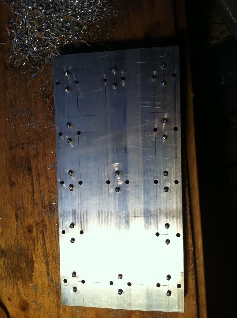
Heatsink marked out for tapping. I also did a diode check on all the LEDs. All the XPGs lit up and most of the XML did as well except for a few. Turns out the +/- on a few of them is printed backwards. I'll have to keep that in mind for when I mount and wire them so I don't fry those LEDs. I have to say I'm a bit disappointed by that. At $7 a LED there shouldn't be problems like that, but I'll make due.
All my LEDs laid out. 24 XPG and 28 XML. 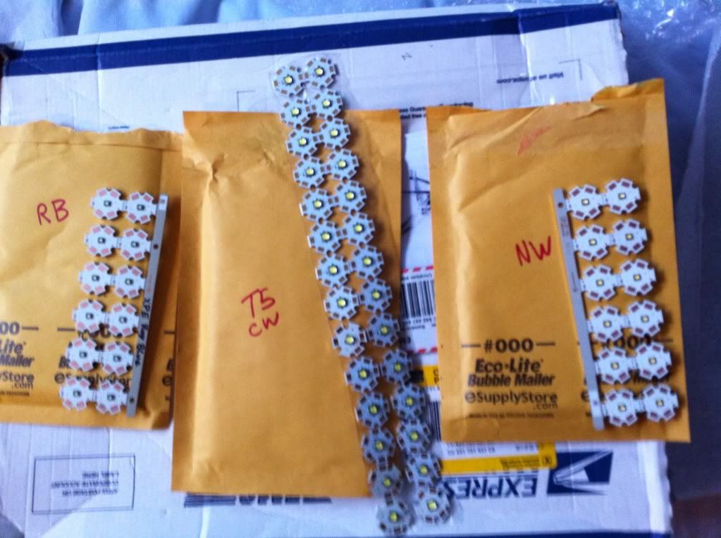 Thermal paste (they sent me 3 extra I think) and lenses. 60 degree for the XPG and 40 degree for the XML. 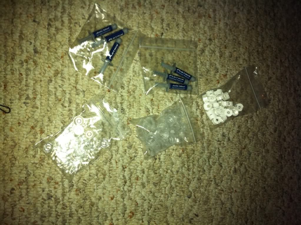 Here is my arduino with the LED screen on the left. I don't think I'll use the screen but I have it anyway. There is also the real time clock so I can set and have the arduino run properly. 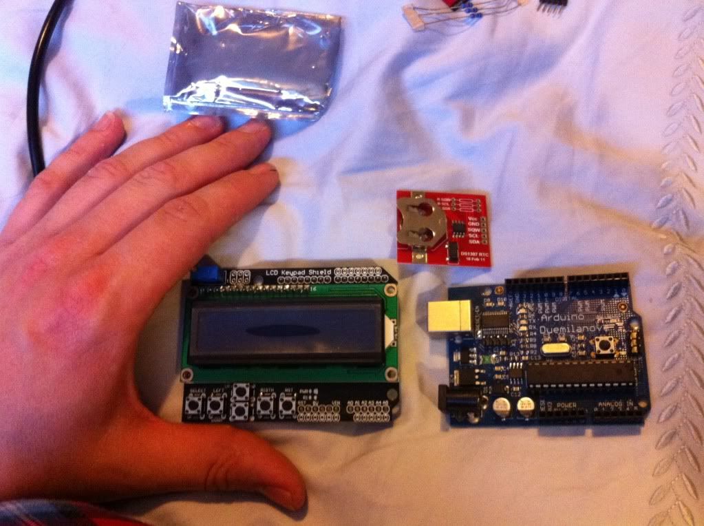 These two photos are my Meanwell power supplies. Each can supply up to 13 amps, 24vdc. I will probably only need one for my build. 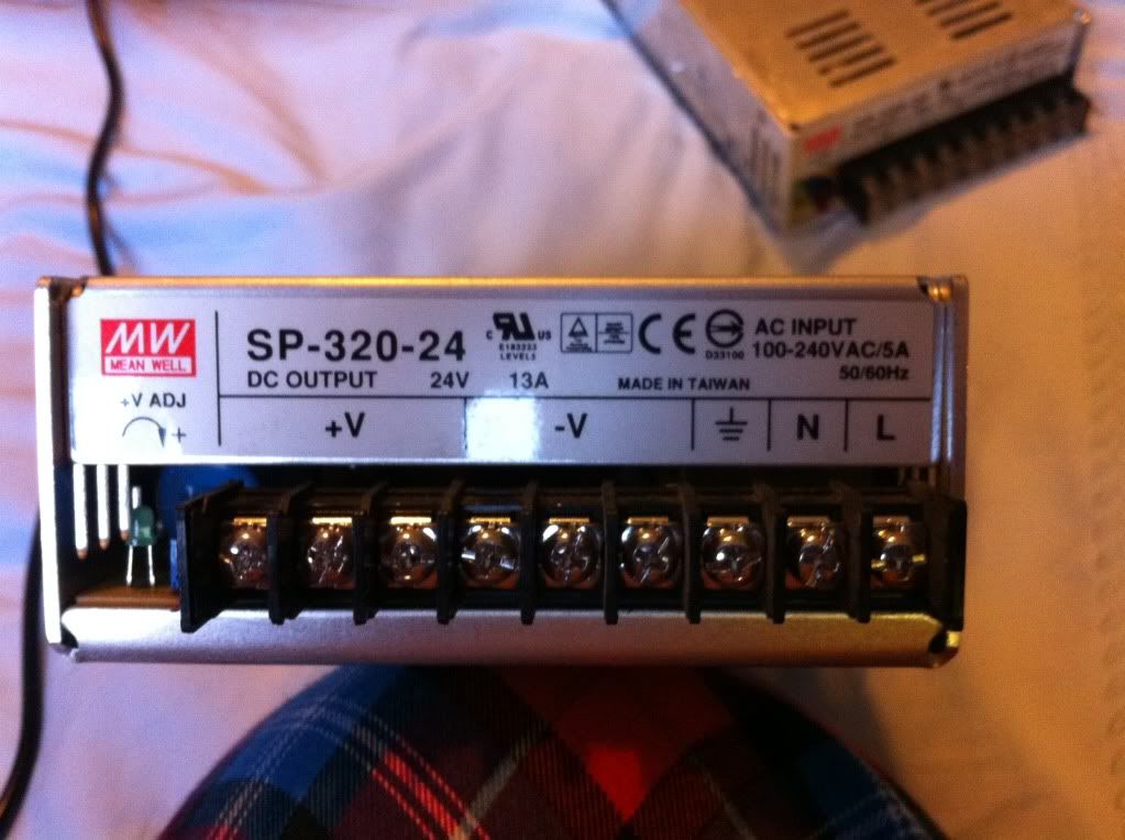 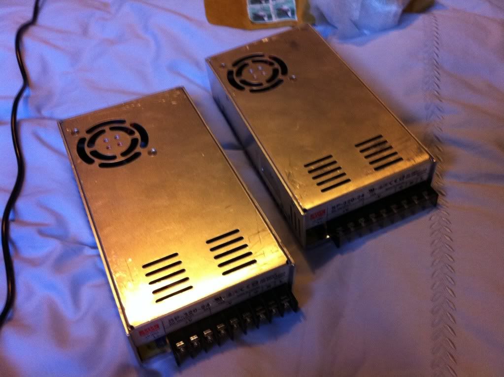 Here is the heart and soul of this build. My drivers... thanks a bunch to Aaron who kindly helped me out with these. It was around $140 for a supply and two boards which will drive 48 XPG. You could probably squeeze 56 XML onto two boards. This is pretty close to the price of 4 meanwells except my mine will be dimmable in groups of 6/7 and they wont clip out at 15%. Aaron has informed me they should come on at around 2% when the Leds are still cold and dim all the way off once they are warmed up. The boards also have outputs for 12v fans and I can power my Arduino as well. There are analogue trim pots to adjust the max current to less than 1000mA and also pwm inputs for the dimming control. If I don't use a pwm signal I can bypass the pwm with a jumper so the lights simply come on if I choose to use a basic timer. 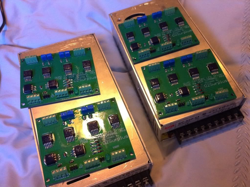 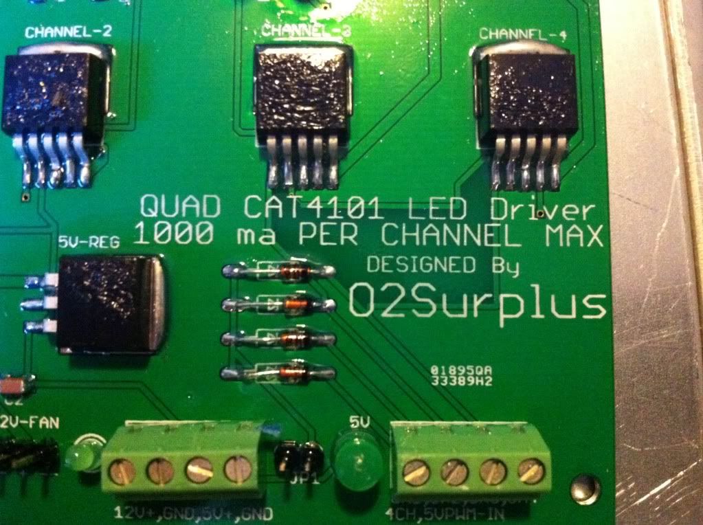
|
|
|
|
|
10/06/2011, 08:45 PM
|
#5 |
|
Registered Member
Join Date: May 2011
Posts: 74
|
First I tested all my LEDs with the diode check to insure the polarity was marked correctly and ensure they all light up.
Marking out my heat sinks for the XMLs. You can see where my CW will be going. I wrote CW next to the cross hairs. The other six circled cross hairs around the perimeter of the sink will be royal blues and neutral whites. Obviously three of each isn't ideal so they will alternate in a triangle pattern. The next heat sink will be spun 180 degrees so the RB will zig zag all the way down the tank. I'm trying to get decent coverage. 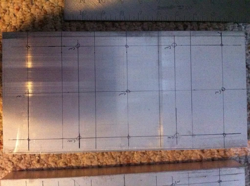 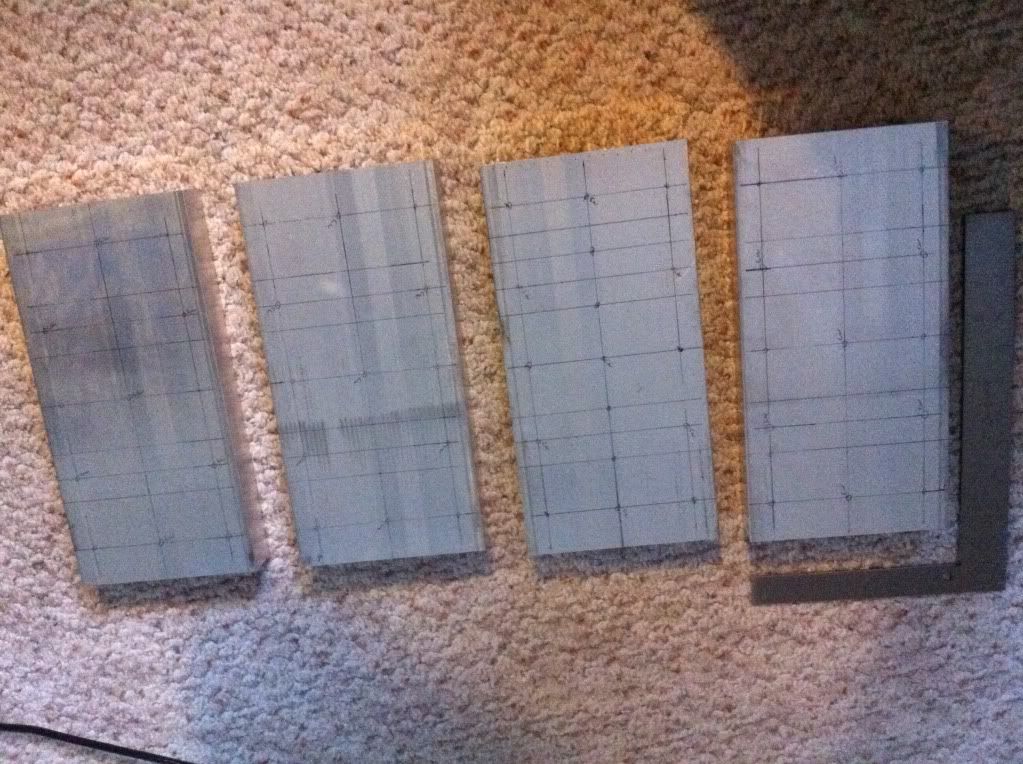 Next I had to mark out my holes that need to be tapped. I have it planned so all my screw will be down a channel between fins. The channels on each side of that channel will have all my wiring. I will drill more holes so I can feed the wire through and have most of it hidden. All the solder points and screws will be squared up. No zig zagging for me. First I did up a template. I should have marked the holes for my wiring while I was at it but it didn't occur to me till I was done. I also should have made up a template that I could tape to the sink and used a punch to mark my holes. Some of my stars needed to be filed out a touch to fit between the screws properly. Live and learn. Lining up a star and punching holes in cardboard: 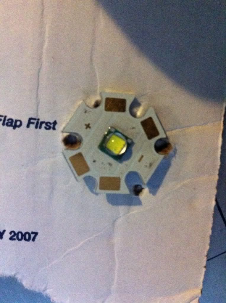 Test fit: 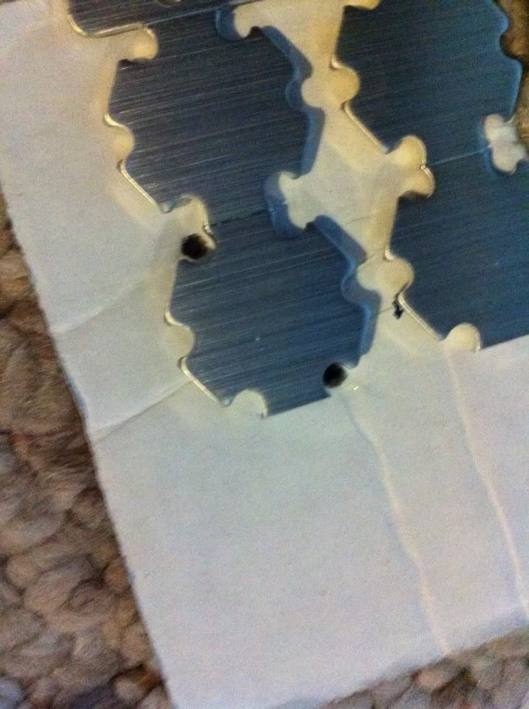 Double check: 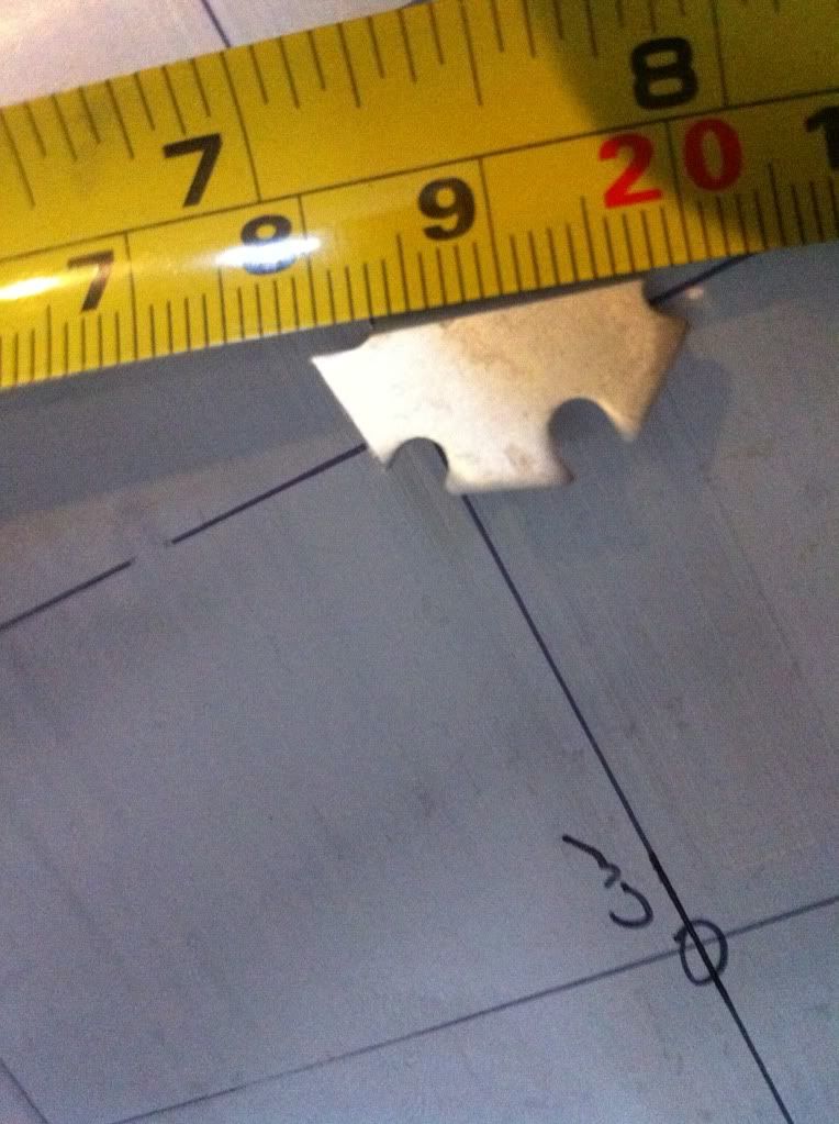 Triple check: 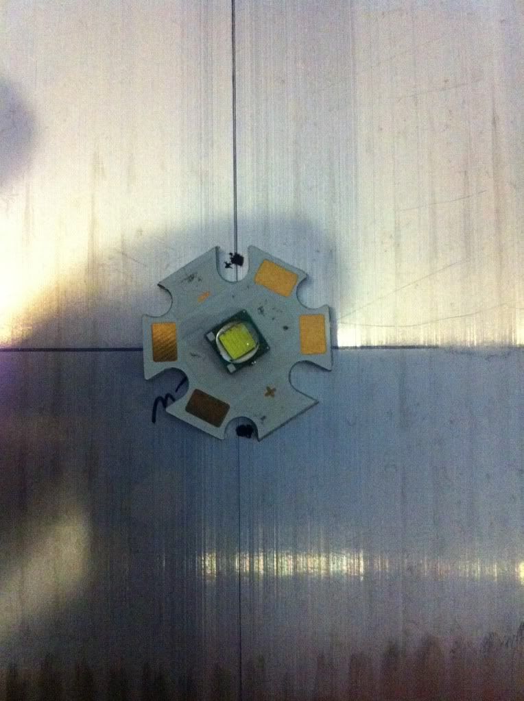 Finally all four sinks are marked out. I got tired so I'll mark the wiring holes another day. 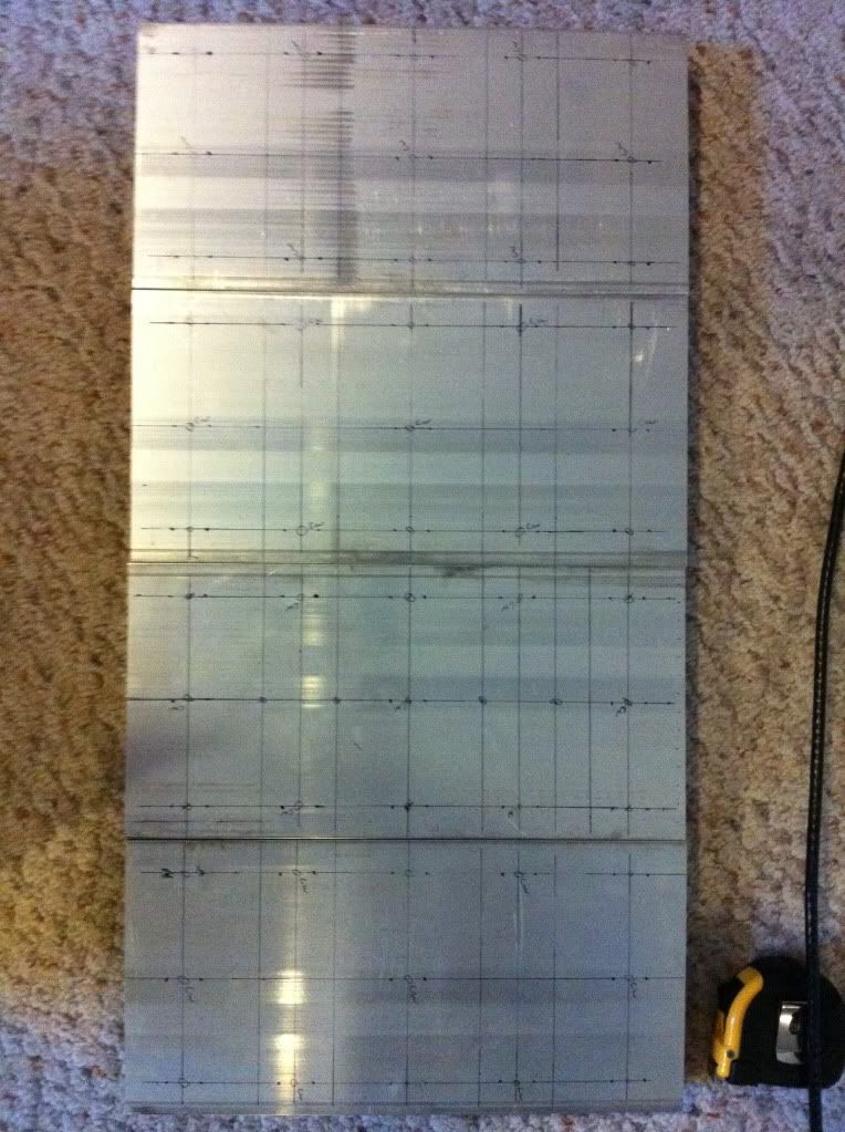 That's all I got done for now. |
|
|
|
|
10/06/2011, 08:49 PM
|
#6 |
|
Registered Member
Join Date: May 2011
Posts: 74
|
This isn't quite the finished product. Just after I got this far I used the 1/4" bit to ream out the 3/16" hole. There were a lot of burrs between the fins which just wouldn't do. I should have done that before I tapped the holes because shaving may have gotten in there. Too late now.
 And since I broke two taps I had to move two stars over about 2mm which totally ruins everything. It was going to line up so nice too. I tried my best to get out the tap but once it broke the tips were just too brittle to grab. I only had about .5mm sicking out each side of the heat sink so I just left them. I tried drilling them out which was pretty futile. Taps are made to do the drilling so no such luck with that. 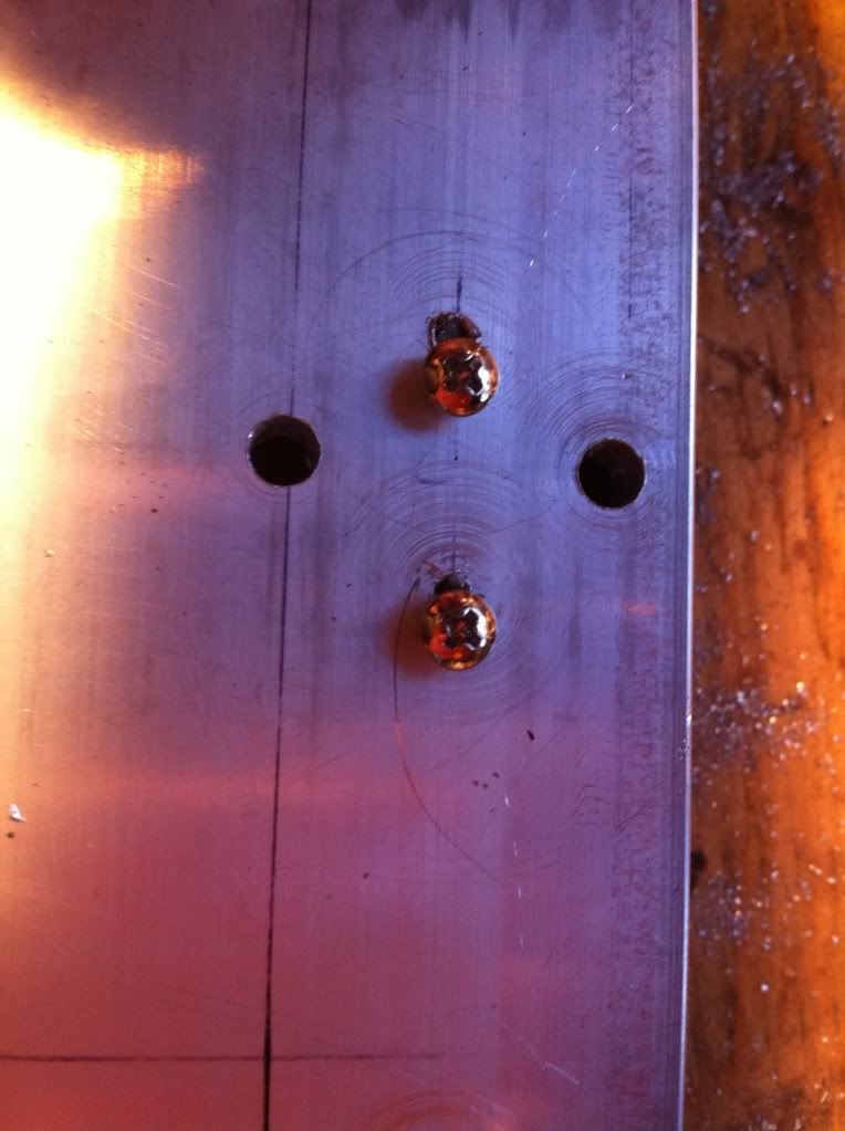 I'm pretty confident that if I really took my time I could have tapped every hole with one tap, but it took me about 7 hours total. Just the tapping. My patience was tested by the end of it and in retrospect, I should have paid a machine shop to do it. I would've charged myself nearly $300 for the time. However, in the end I'm pretty happy with the result and I will do it again on my next build. It's just so clean looking and I wont have epoxy all over my heat sink. Or wires! |
|
|
|
|
10/06/2011, 08:52 PM
|
#7 |
|
Registered Member
Join Date: May 2011
Posts: 74
|
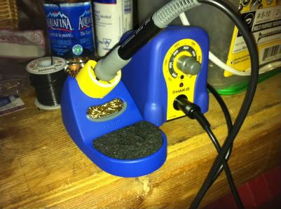
I was looking for a soldering station and while I was browsing the Wellers, the shop worker recommended a Hekko. It was the same price but had a few features I like such as temp readings in both ferinheit and celcius. He also said he found it doesn't drop it's temp like the Wellers apparently do. I can't comment because I have no experience with either. All I know is the Hekko worked well for me. I set the temp to around 850F because 750F wasn't quite hot enough.
 I pre ran all my wiring so I didn't waste any and I could think about my layout. I wanted all the connections to be somewhat close together so the harness wouldn't need to split all over the place. I'm aiming to keep everything clean. The wiring jumping fins looks messy, but I won't be seen when I'm done. 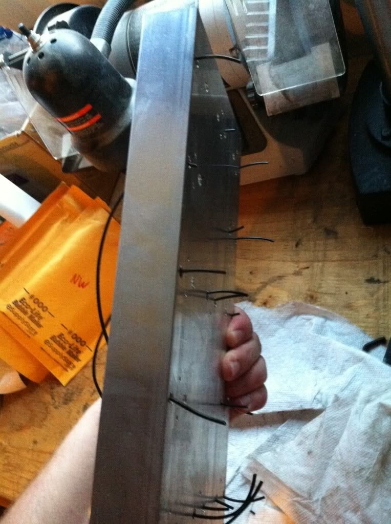 Here is the sink all wired and soldered up. I wish I could have ran the wire into the LEDs differently, but I didn't have as much room as I thought I would and I had to make due. I didn't want any shorts and the stars aren't very forgiving. 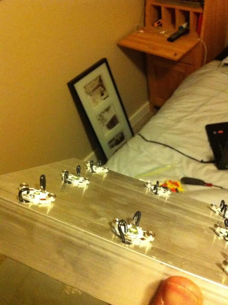 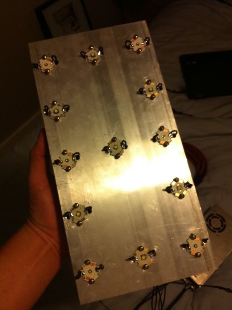 Here you can see the wiring harness I quickly did up. Each wire will go into a disconnect for easy pendant removal. I labelled each wire within the fins with a white (CW), yellow (NW) or blue (RB) piece of heat shrink for identification. Once the wires come out of the bundle they are marked with the string colour and a red (+) or grey (-) piece of heat shrink for easy hookup. 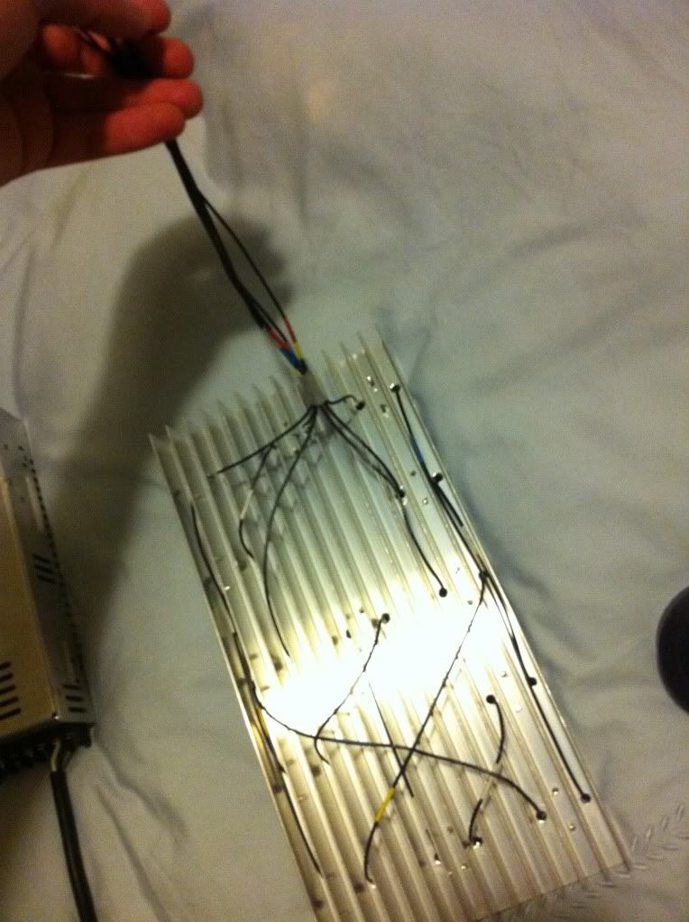
|
|
|
|
|
10/06/2011, 08:52 PM
|
#8 |
|
Registered Member
Join Date: May 2011
Posts: 74
|
Did some more this weekend. I was looking for a soldering station and while I was browsing the Wellers the shop worker recommended a Hekko. It was the same price but had a few features I like such as temp readings in both ferinheit and celcius. He also said he found it doesn't drop it's temp like the Wellers do. I can't comment because I have no experience with either. All I know is the Hekko worked well for me. I set the temp to around 850F because 750F wasn't quite hot enough.
I pre ran all my wiring so I didn't waste any and I could think about my layout. I wanted all the connections to be somewhat close together so the harness wouldn't need to split all over the place. I'm aiming to keep everything clean. The wiring jumping fins looks messy, but I won't be seen when I'm done. Here is the sink all wired and soldered up. I wish I could have ran the wire into the LEDs differently, but I didn't have as much room as I thought I would and I had to make due. I didn't want any shorts and the stars aren't very forgiving. Here you can see the wiring harness I quickly did up. Each wire will go into a disconnect for easy pendant removal. I labelled each wire within the fins with a white (CW), yellow (NW) or blue (RB) piece of heat shrink for identification. Once the wires come out of the bundle they are marked with the string colour and a red (+) or grey (-) piece of heat shrink for easy hookup.
|
|
|
|
|
10/06/2011, 08:53 PM
|
#9 |
|
Registered Member
Join Date: May 2011
Posts: 74
|
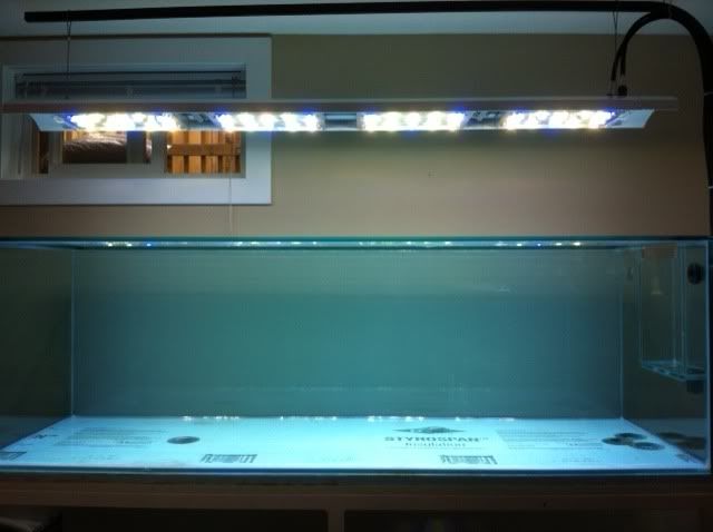
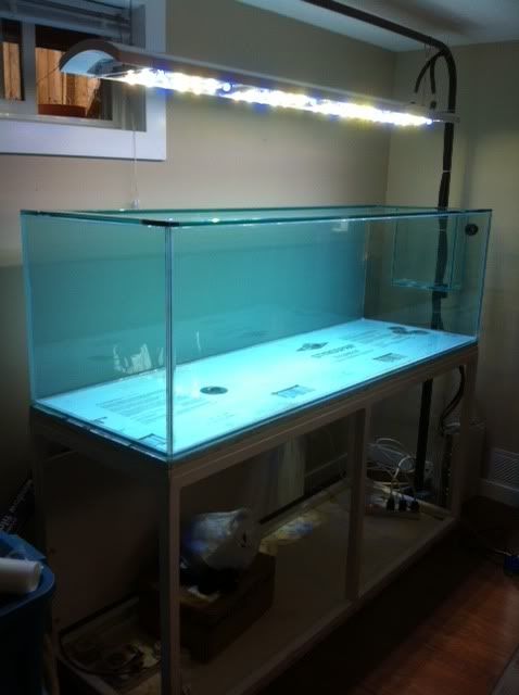
Now these pics are just to show some example of the colour and power of this baby. I did have to string together the NW and RB as I only have three per pendant and I wanted to properly load the string. In the first pic of only the RB and NW and it's really blue.
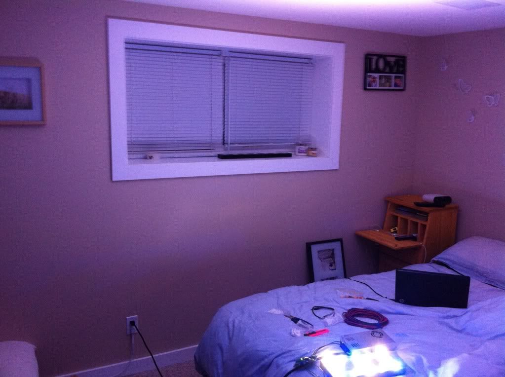 This next one is the CW turned up with RB + NW turned down. 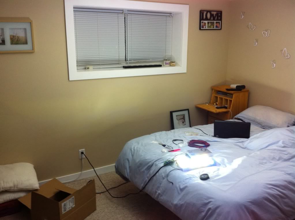 Next we have the fixture dimmed and then the fixture full blast. It's about midnight and the lights are off with a pitch black room to start. 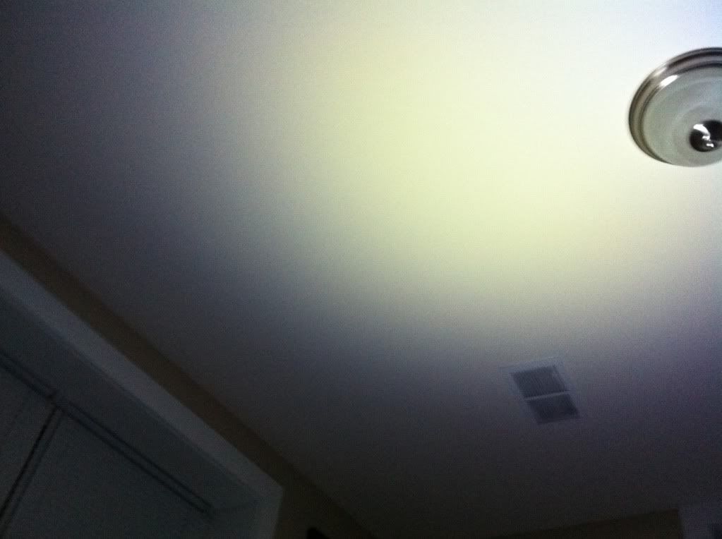  My iphone messes with the contrast a bit in the photos, but it's not a terrible representation of what I saw. |
|
|
|
|
10/06/2011, 08:57 PM
|
#10 |
|
Registered Member
Join Date: May 2011
Posts: 74
|
I finished 90% of the soldering, I just have to finish the wiring harness. I'm leaving that until I decide on my enclosure design. Something fantastic happened at work the other day, and my design is once again undecided.
Originally I was going to copy this fixture, but do four pendants with the same look instead of one. 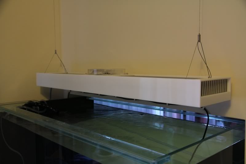 Then because fabricating them would be a pain with my limited resources, and four would be a pain to hang with cable from EMT (can't use the rented ceiling) I was thinking straight up copying the design would be ideal. I already have all the acrylic. I scored it free from my local shop a few weeks ago. Then my boss had the guys demo a bunch of lighting and he said I could pillage the garbage before it went out the door. I scored 44... yes 44 polished aluminum reflectors from t5 fixtures, and these two housings... 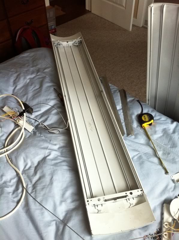 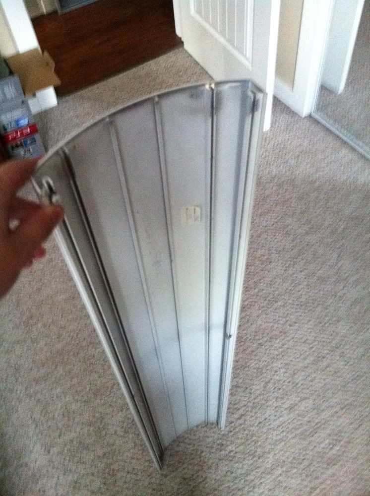  With a bit of aluminum angle I can make brackets to hold the heat sinks and cap the ends at the same time. There are slots that are designed to be screwed into, so the build would be easy as pie. My issue is that I need a housing that is five feet long at minimum. So I checked at work again and found some one piece, eight foot housings. I brought two of them home with me today, as long as come adjustable hanging gear, screws, etc. |
|
|
|
|
10/06/2011, 09:01 PM
|
#11 | |
|
Registered Member
Join Date: May 2011
Posts: 74
|
Quote:
The first half a dozen posts should give you some eye candy! |
|
|
|
|
|
10/06/2011, 09:36 PM
|
#12 |
|
Registered Member
Join Date: Aug 2011
Location: "The Land of Fruits & Nuts"
Posts: 879
|
Oh....so now I see how it's gonna be. Hanging out with the Reefers are Ya! What is it? Planted Tank people not "cool" enough for Ya!
 (jk) Nice job man! I wish you could work faster!(jk) I can't wait to see your tank up and running, It's gonna look good. (jk) Nice job man! I wish you could work faster!(jk) I can't wait to see your tank up and running, It's gonna look good.
|
|
|
|
|
10/06/2011, 09:42 PM
|
#13 |
|
Registered Member
Join Date: Jul 2010
Location: Tucson,AZ
Posts: 430
|
awesome pics! ok.. so being still a newb... where in the world do you learn how to do all this LED stuff? Im pretty capable with most things but i have no idea where i would start to learn any of this stuff. is there like a link or a book or something that i can learn the technical stuff that has to do with LEDs? a college class? Something!! hahaha
|
|
|
|
|
10/06/2011, 09:57 PM
|
#14 | |
|
Registered Member
Join Date: May 2011
Posts: 74
|
Quote:

|
|
|
|
|
|
10/06/2011, 10:09 PM
|
#15 | |
|
Registered Member
Join Date: May 2011
Posts: 74
|
Quote:
I only know what I know from researching so much. I've also asked a lot of questions. My build still ended up being a huge learning experience. I'm doing a lot of things people say not to do, but I've never seen anyone actually do it, so I want to see what the results are. With technology that isn't very widespread, sometimes you have to go out on a limb. I'm an electrician, but honestly, if you don't understand how to wire a string, you are not prepared to start the project. A series circuit is one of the most basic circuits. You really don't even need to do calculations if you don't want to, as most of the information is readily available. I am breaking many rules/ common practices... mixing optics, mixing types of LEDs, running my LEDs at higher currents, using wide spacing between LEDs... from what I've read, these are all things I should try to avoid. However, I figure I live and learn. There are things I want to try, and if it works out great. If not... well... they told me so. |
|
|
|
|
|
10/08/2011, 04:11 PM
|
#16 |
|
Registered Member
Join Date: May 2011
Posts: 74
|
I have a few videos to share. The first two show my method for tapping heatsinks, the last is just one I did while I was testing all the components of my build. I have a few kinks and issues to work out, but in general it's going pretty good.
Excuse my spaciness in the last video, I was kinda out of it. I also apologize for the fingers in the frames. How to tap part 1 How to tap part 2 Leds fired up! |
|
|
|
|
06/04/2012, 04:48 PM
|
#17 |
|
Registered Member
Join Date: May 2011
Posts: 74
|
|
|
|
|
|
06/04/2012, 05:27 PM
|
#18 |
|
Registered Member
Join Date: May 2011
Posts: 74
|
So, a member on my main forum built a DIY par meter and we consider it to be "good enough" so it bought one to take measurements. Thought other members here may be interested. Here's a vid I made I me taking measurements. Please excuse the freshwater, I just love Reef Central for the abundant knowledge. I do planted tanks myself.
http://www.youtube.com/watch?v=nYymP...e_gdata_player |
|
|
|
 |
|
|
 Similar Threads
|
||||
| Thread | Thread Starter | Forum | Replies | Last Post |
| DIY Led Build of the Month | plankton99 | Do It Yourself |
11 | 11/20/2011 08:21 AM |
| DIY Led Fixture. How Many led for 120 Gal (5 foot) | beachjf | Do It Yourself |
0 | 06/16/2011 02:10 PM |
| LED Build Bio Cube 29 Pictures | Doughboy911 | Do It Yourself |
2 | 06/09/2011 07:31 AM |
| led build for corner tank i want do this right and other? for tank | divinedragon13 | Do It Yourself |
0 | 06/01/2011 06:52 PM |
| The start of an LED build | Renton777 | Do It Yourself |
5 | 01/14/2011 09:58 PM |


