
|
|
 04/25/2016, 07:31 PM
|
#276 |
|
Registered Member
Join Date: Feb 2016
Location: Arnold
Posts: 28
|
Have you ever looked @ the Richtek 8471 as a possible driver???
Contemplating a 7 driver board w/ethernet plug for PWM. |

|

|
|
04/25/2016, 08:43 PM
|
#277 | |
|
100-mile-commuter
Join Date: Dec 2004
Location: almost nevada
Posts: 4,721
|
Quote:
__________________
Custom electronics purveyor. blueAcro.com Current Tank Info: 90g SPS+mixed reef (10 yrs): LEDBrick LEDs, 40g custom sump, Ca reactor, chiller, Vortech, lots of custom electronics |
|
|
|
|
|
04/26/2016, 03:46 PM
|
#278 | |
|
Registered Member
Join Date: Mar 2013
Posts: 113
|
Quote:
|
|
|
|
|
|
04/26/2016, 04:01 PM
|
#279 | |
|
Registered Member
Join Date: Sep 2003
Location: North Carolina
Posts: 20,050
|
Quote:
How to figure out resistor/cap/inductor values,etc..
__________________
Who me? |
|
|
|
|
|
04/26/2016, 04:31 PM
|
#280 | |
|
Registered Member
Join Date: Mar 2013
Posts: 113
|
Quote:
|
|
|
|
|
|
04/26/2016, 06:43 PM
|
#281 | |
|
Registered Member
Join Date: Feb 2016
Location: Arnold
Posts: 28
|
Quote:
A longer document from TI with calculation examples. I was driving for a very low part count so no TI drivers. I have not etched a copper board since 1984. It was a frequency counter with like a 9 digit display. All through hole components at that. Now I have to rethink surface mount devices and configuration. I have been researching for about 1 year now and am ready. Up until now I have been using all LDD drivers on boards with sockets. LDD's cost $6 each, I can build a driver for $2.31 each plus cost of boards. I may not save money when it's done but it keeps my brain ticking. I belong to many forums, most inspired with DIY from several people here. I am an AutoCAD geek since version 8 I think on 5.25 floppies. No one wants to build a board from ACAD files though. |
|
|
|
|
|
04/26/2016, 08:19 PM
|
#282 |
|
100-mile-commuter
Join Date: Dec 2004
Location: almost nevada
Posts: 4,721
|
I made a calculator sheet based on the formulas:
https://docs.google.com/spreadsheets...it?usp=sharing I haven't double checked the math, but it sorta looks right. Put data in the first set of green fields, see minimum inductor value, put a real part (inductor) in the second set of fields, and check that the timing is ok (must be greater than the listed time at the top)
__________________
Custom electronics purveyor. blueAcro.com Current Tank Info: 90g SPS+mixed reef (10 yrs): LEDBrick LEDs, 40g custom sump, Ca reactor, chiller, Vortech, lots of custom electronics |
|
|
|
|
04/26/2016, 11:13 PM
|
#283 | |
|
100-mile-commuter
Join Date: Dec 2004
Location: almost nevada
Posts: 4,721
|
Quote:
Boards from DXF or DWG CAD files would be unusual. Gotta generate Gerber files, which its self is a 1980s file format for Gerber made photo plotters that just became the defacto standard over time. Eagle and DIPTrace aren't that bad in their free form. KiCad has a pretty esoteric interface but is capable.
__________________
Custom electronics purveyor. blueAcro.com Current Tank Info: 90g SPS+mixed reef (10 yrs): LEDBrick LEDs, 40g custom sump, Ca reactor, chiller, Vortech, lots of custom electronics |
|
|
|
|
|
04/27/2016, 08:59 AM
|
#284 |
|
100-mile-commuter
Join Date: Dec 2004
Location: almost nevada
Posts: 4,721
|
One calculation error in the spreadsheet (missed a zero for displaying nanoseconds). I've also linked in a few reasonable part choices.
The sweet spot is likely with a 33uH inductor.
__________________
Custom electronics purveyor. blueAcro.com Current Tank Info: 90g SPS+mixed reef (10 yrs): LEDBrick LEDs, 40g custom sump, Ca reactor, chiller, Vortech, lots of custom electronics |
|
|
|
|
04/28/2016, 08:00 PM
|
#285 |
|
Registered Member
Join Date: Mar 2013
Posts: 113
|
first go at a driver board using the rt8471, i need to do some tweaking with the connectors. and do some labeling
|
|
|
|
|
04/28/2016, 10:59 PM
|
#286 |
|
100-mile-commuter
Join Date: Dec 2004
Location: almost nevada
Posts: 4,721
|
I assume you're planning to get the boards manufactured as opposed to home etch? If so, there are bunch of tweaks to ensure more success in the design, since the converter runs at a moderate frequency (500kHz).
First off, the paths between the diode, LX pin, inductor, and Vin and Ground are critical and carry high current peaks. This means keep the layout direct and very compact (all parts close), with as much copper as you can reasonably fit to connect them. In Eagle, use the copper pour / polygon pour: https://learn.sparkfun.com/tutorials...ishing-touches As for the ground, my suggestion would be to use the entire bottom of the board with one pour as the ground, and connect with one or more vias from each top-side ground pin or node to the bottom. This also includes the center thermal pad of the chip - putting a grid or 2x2 of vias under the driver IC to the bottom plane is thermally better than just using the top copper. These are OSHPark images, but you can see the vias (black dot meaning drill) and copper pours: 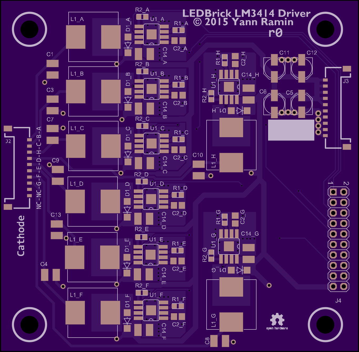 Also an extreme 5 amp variant. The paths between Q1, D1, L1 and R1 (including the kelvin connection) are the ones to watch for: 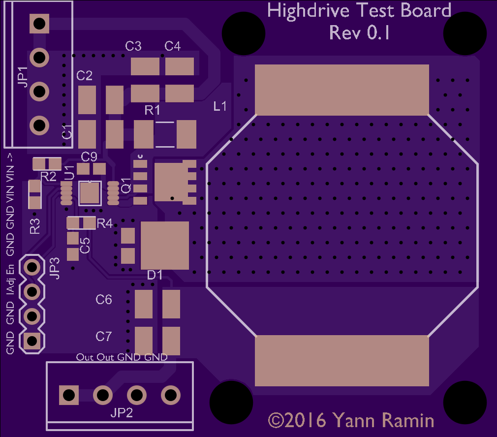 As for the kelvin connection to the sense resistor, here is an illustration: 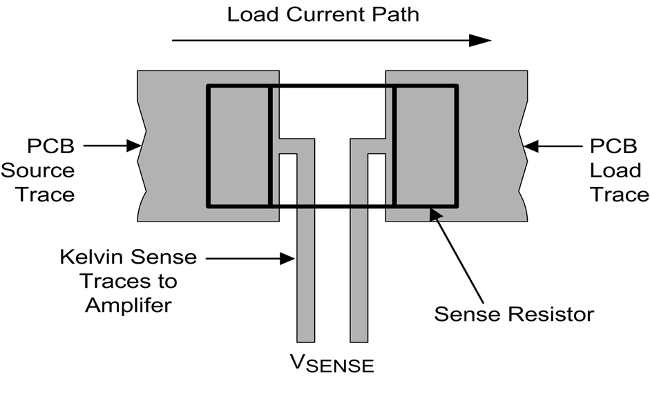
__________________
Custom electronics purveyor. blueAcro.com Current Tank Info: 90g SPS+mixed reef (10 yrs): LEDBrick LEDs, 40g custom sump, Ca reactor, chiller, Vortech, lots of custom electronics |
|
|
|
|
04/28/2016, 11:08 PM
|
#287 |
|
100-mile-commuter
Join Date: Dec 2004
Location: almost nevada
Posts: 4,721
|
Note that the designs I showed aren't totally the same layout - the LM3414 is a low-side switcher, and doesn't have a sense resistor. The LM3409 is a high-side switcher, so the order of the diode, switch and inductor is reversed.
I think if anything moving everything closer together and getting good ground and power connections would be plenty in this design.
__________________
Custom electronics purveyor. blueAcro.com Current Tank Info: 90g SPS+mixed reef (10 yrs): LEDBrick LEDs, 40g custom sump, Ca reactor, chiller, Vortech, lots of custom electronics |
|
|
|
|
04/29/2016, 05:23 PM
|
#288 |
|
Registered Member
Join Date: Mar 2013
Posts: 113
|
made a couple of adjustments, this is the oshpark image
|
|
|
|
|
04/29/2016, 05:47 PM
|
#289 |
|
100-mile-commuter
Join Date: Dec 2004
Location: almost nevada
Posts: 4,721
|
LEDBrick Project - DIY pendant w/ pucks
Looking good!
I'd avoid running the PWM trace in parallel with either of the LED traces - it's easy for the much larger current swings to couple onto the signal line. Probably use a via to push it to the bottom layer and away from the power traces. Also, might as well make the power traces 20+ mils where you have the room.
__________________
Custom electronics purveyor. blueAcro.com Current Tank Info: 90g SPS+mixed reef (10 yrs): LEDBrick LEDs, 40g custom sump, Ca reactor, chiller, Vortech, lots of custom electronics |
|
|
|
|
04/29/2016, 06:28 PM
|
#290 | |
|
Registered Member
Join Date: Mar 2013
Posts: 113
|
Quote:
|
|
|
|
|
|
04/30/2016, 10:08 AM
|
#291 |
|
Registered Member
Join Date: Mar 2013
Posts: 113
|
The one I am using is the rt8471
|
|
|
|
|
05/01/2016, 05:41 PM
|
#292 |
|
100-mile-commuter
Join Date: Dec 2004
Location: almost nevada
Posts: 4,721
|
Just for grins, I decided to knock up an RT8471 design too. First stumbling block is the lack of actual solder footprints in the datasheet. I recommend checking against their all in one footprint guide:
http://www.richtek.com/~/media/Richt...0330.pdf?la=en
__________________
Custom electronics purveyor. blueAcro.com Current Tank Info: 90g SPS+mixed reef (10 yrs): LEDBrick LEDs, 40g custom sump, Ca reactor, chiller, Vortech, lots of custom electronics |
|
|
|
|
05/01/2016, 07:22 PM
|
#293 |
|
Registered Member
Join Date: Mar 2013
Posts: 113
|
can you use eagle library or is it different for the program you use?
|
|
|
|
|
05/01/2016, 07:24 PM
|
#294 | |
|
100-mile-commuter
Join Date: Dec 2004
Location: almost nevada
Posts: 4,721
|
Quote:
I can import eagle libraries and files, but I usually, as a matter of habit, build footprints per vendor or part anyway. I'm sure others would love it though - perhaps put it on github?
__________________
Custom electronics purveyor. blueAcro.com Current Tank Info: 90g SPS+mixed reef (10 yrs): LEDBrick LEDs, 40g custom sump, Ca reactor, chiller, Vortech, lots of custom electronics |
|
|
|
|
|
05/01/2016, 07:39 PM
|
#295 |
|
Registered Member
Join Date: Feb 2016
Location: Arnold
Posts: 28
|
I am still working on this idea.
Checking it out in ACAD. Not sure where I am going yet. I chose a different 5 pin package of the 8471.  Found a 14 pin Phoenix terminal block for 7 drivers and an RJ45 for PWM. Any thoughts on this? Board dims are 100x50mm. Ground and +24VDC bus will be on the terminal side of the board. Still a pulldown resistor of 10K for PWM loss??? Last edited by Maryland Guppy; 05/01/2016 at 07:42 PM. Reason: edit |
|
|
|
|
05/01/2016, 09:12 PM
|
#296 |
|
100-mile-commuter
Join Date: Dec 2004
Location: almost nevada
Posts: 4,721
|
Watch out for the SOT-23-5 package, it will be thermally limited since the switch in this unit isn't fantastic and there is no good thermal path in that tiny package. Also, I noticed that the MSOP-8 and the SOT-23-5 are the only ones in stock, the SOP-8 isn't available.
If you don't add a pulldown, it looks like the ADJ pin is internally biased up, so a pull down would keep the LEDs off instead of on. Otherwise your design is very compact and neat, like it! I can't guarantee I can convert a DXF to gerber files, but I can give it a shot. Here is an MSOP-8 layout I'm working on - single channel: 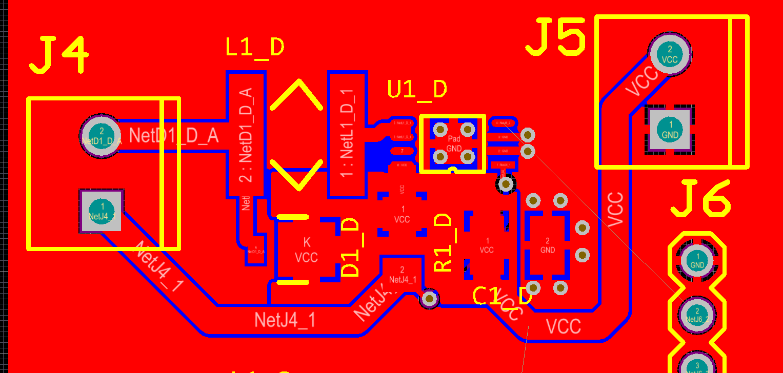 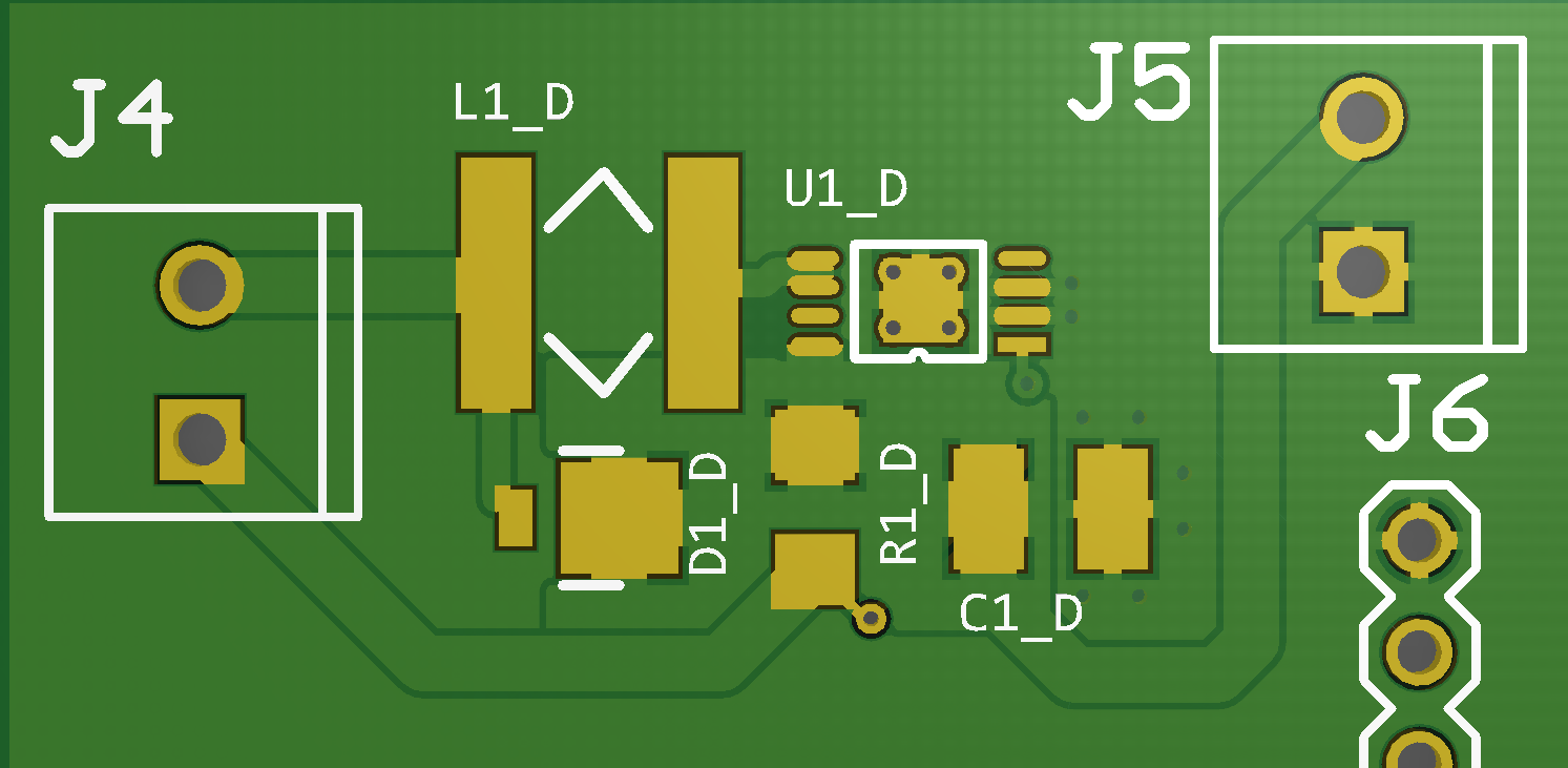
__________________
Custom electronics purveyor. blueAcro.com Current Tank Info: 90g SPS+mixed reef (10 yrs): LEDBrick LEDs, 40g custom sump, Ca reactor, chiller, Vortech, lots of custom electronics |
|
|
|
|
05/01/2016, 09:13 PM
|
#297 | |
|
Registered Member
Join Date: Apr 2013
Posts: 1,793
|
Quote:
Sorry just an annoying sore point for me. I think they are a good idea but should be optional-able.. |
|
|
|
|
|
05/01/2016, 09:20 PM
|
#298 |
|
100-mile-commuter
Join Date: Dec 2004
Location: almost nevada
Posts: 4,721
|
Here are the parts I'm currently using:
http://www.digikey.com/product-detai...1-1-ND/5820085 http://www.digikey.com/short/3jwtnj http://www.digikey.com/product-detai...ICT-ND/1091682 http://www.digikey.com/product-detai...3-1-ND/3969145 http://www.digikey.com/product-detai...2-1-ND/3889378 Capacitor is mainly since I already have a ton of them.
__________________
Custom electronics purveyor. blueAcro.com Current Tank Info: 90g SPS+mixed reef (10 yrs): LEDBrick LEDs, 40g custom sump, Ca reactor, chiller, Vortech, lots of custom electronics |
|
|
|
|
05/01/2016, 09:50 PM
|
#299 |
|
Registered Member
Join Date: Feb 2016
Location: Arnold
Posts: 28
|
Her is where I am at.
Opted for the TSOT23-5 package. I picked the 100UH inductor based on a datasheet from Richtek. Will try to remember where and post link. For RSense @ .15 1% to run 3 watt LED's @ 667mA See anything flawed in my layout??? 
|
|
|
|
|
05/01/2016, 10:13 PM
|
#300 | |
|
Registered Member
Join Date: Feb 2016
Location: Arnold
Posts: 28
|
Quote:
If it goes any further I am looking at some of the free software out there. 2 layer easy board, software free for my limited app. Thinking of adding a fan control on this board just to keep the drivers cool. There is room with minimal re-arranging. This is what I am typically driving on fresh water planted tanks. Run LDD's at 52VDC to run 14-3 watt lamps. New arrangement would require 2 drivers @ 24VDC. 
|
|
|
|
|
 |
|
|


