
|
|
|
|||||||
 |
| Thread Tools |
 09/13/2010, 08:58 PM
|
#126 |
|
Registered Member
Join Date: Nov 2009
Location: Nice, French riviera, France
Posts: 21
|
Hi
great job but. I haven't realy understand,the resistor and the led for exemple are not conected to the ground on the eagle file. And how do you communicate with the pc to send the code in the atmega. Do you need to plug something (a usb interface for example). Thanx you to answer to my stupid questions. |

|

|
|
09/13/2010, 11:02 PM
|
#127 |
|
Registered Member
Join Date: Apr 2010
Posts: 60
|
I took a look at the code. I think that there are some optimizations that could be made to the logic that would allow it to be a bit more modular. I will PM you in the next couple of days when I get a chance.
|
|
|
|
|
09/13/2010, 11:43 PM
|
#128 |
|
Premium Member
 Join Date: Feb 2001
Location: Park Ridge
Posts: 2,232
|
I need a bit of help with http://code.google.com/p/typhon-reef/
For some reasons I found the files but cannot open the .brd file and others. What software do I need? Sorry for the questions as I grew up with a Timex Sinclair and a no kidding cassette tape for a hard drive. Bill
__________________
NKAWTG Current Tank Info: 570 Soft/LPS, 330SPS & 440 refug |
|
|
|
|
09/13/2010, 11:46 PM
|
#129 |
|
Registered Member
Join Date: Nov 2009
Location: Nice, French riviera, France
Posts: 21
|
I open it with "eagle"
|
|
|
|
|
09/14/2010, 06:39 AM
|
#130 | |||||
|
Team RC Member
Join Date: Sep 2003
Location: NY
Posts: 17,749
|
Quote:
 Quote:
http://www.sparkfun.com/commerce/pro...oducts_id=9718 http://www.sparkfun.com/commerce/pro...oducts_id=9115 http://www.moderndevice.com/products/usb-bub (this is the one I use) Or if you are adventurous, you can use any generic ($2 on eBay) USB-serial cellphone cable, hack the wiring to a pin header, and dig for the correct drivers. Quote:
Quote:
Quote:
http://www.cadsoftusa.com/freeware.htm People not familiar with Eagle can get started by working through the tutorials on basic Eagle functionality hosted by Sparkfun as part of their "Beginning Embedded Electronics" series: http://www.sparkfun.com/commerce/tut...torials_id=108
__________________
Inconveniencing marine life since 1992 "It is my personal belief that reef aquaria should be thriving communities of biodiversity, representative of their wild counterparts, and not merely collections of pretty specimens growing on tidy clean rock shelves covered in purple coralline algae." (Eric Borneman) |
|||||
|
|
|
|
09/14/2010, 07:51 AM
|
#131 | |
|
Registered Member
Join Date: Nov 2009
Location: Nice, French riviera, France
Posts: 21
|
Quote:
I'll take the same as yours Can you give me address of manufacturer pcb (maybe by PM). Thank you again |
|
|
|
|
|
09/14/2010, 08:04 AM
|
#132 |
|
Team RC Member
Join Date: Sep 2003
Location: NY
Posts: 17,749
|
actarus, I used seeedstudio to make the prototype PCBs. They have a fixed-price package where boards under 10cm * 10cm are $40 for 10 pieces. If you don't mind the fact that you're getting 10 pieces, this is by far the best price you'll find unless you get up near mass production quantities.
If you only want to order one or two, you might be better off looking at: batchpcb.com http://dorkbotpdx.org/wiki/dorkbotpdx_group_ordering Both of these places basically take one-off hobbyist designs, panelize them, and order in batches. You pay more per square inch than seeedstudio, but you can order one or two boards without worrying about outrageous pricing - most "real" board houses don't even want to make one or two pieces, and they'll charge you an insane amount if they will.
__________________
Inconveniencing marine life since 1992 "It is my personal belief that reef aquaria should be thriving communities of biodiversity, representative of their wild counterparts, and not merely collections of pretty specimens growing on tidy clean rock shelves covered in purple coralline algae." (Eric Borneman) |
|
|
|
|
09/14/2010, 08:27 AM
|
#133 |
|
Registered Member
Join Date: Nov 2009
Location: Nice, French riviera, France
Posts: 21
|
Tanks for the links
|
|
|
|
|
09/15/2010, 04:54 AM
|
#134 |
|
Registered Member
Join Date: Nov 2009
Location: Nice, French riviera, France
Posts: 21
|
Can i use this board to communicate vith the PC ?
http://www.geeetech.com/index.php?ma...4dkag8frhvgdn1  On your board,Dwzm,it's RTS line,here it's RST line.What is the difference between ? I saw on the same website a cheap lcd display , can i use it ? http://www.geeetech.com/index.php?ma...4dkag8frhvgdn1  Thanks |
|
|
|
|
09/15/2010, 07:40 AM
|
#135 | |
|
Registered Member
Join Date: Nov 2009
Location: Nice, French riviera, France
Posts: 21
|
Quote:
|
|
|
|
|
|
09/15/2010, 08:05 AM
|
#136 | |
|
Team RC Member
Join Date: Sep 2003
Location: NY
Posts: 17,749
|
Not sure about that LCD, at least not without modification. It says:
Quote:
Regarding the USB-serial converter you posted - it SHOULD work, but you may have to fiddle to get the auto reset working, and you'll need to get a driver for that device for your OS. The FT232R driver is pretty much available for any OS (or already included in most OSs) and I'm not sure about drivers for that chip. I do know that people have posted about it on the Arduino forums so it is possible. Also strikes me as a little funny that their website is a complete ripoff of Sparkfun!
__________________
Inconveniencing marine life since 1992 "It is my personal belief that reef aquaria should be thriving communities of biodiversity, representative of their wild counterparts, and not merely collections of pretty specimens growing on tidy clean rock shelves covered in purple coralline algae." (Eric Borneman) |
|
|
|
|
|
09/15/2010, 09:12 AM
|
#137 |
|
Registered Member
Join Date: Apr 2010
Location: Texas
Posts: 1,532
|
I have used the SPLC780D based LCDs in place of the HD44780 without issue.
|
|
|
|
|
09/15/2010, 09:15 AM
|
#138 |
|
Team RC Member
Join Date: Sep 2003
Location: NY
Posts: 17,749
|
Then I'm assuming SPLC780D is HD44780 compatible. Good to know. I am surprised they don't come out and say that, since the HD44780 seems to be the name people recognize.
__________________
Inconveniencing marine life since 1992 "It is my personal belief that reef aquaria should be thriving communities of biodiversity, representative of their wild counterparts, and not merely collections of pretty specimens growing on tidy clean rock shelves covered in purple coralline algae." (Eric Borneman) |
|
|
|
|
09/15/2010, 09:28 AM
|
#139 |
|
Registered Member
Join Date: Nov 2009
Location: Nice, French riviera, France
Posts: 21
|
ok thanks you
there is a problem on the code ? Normaly for LCD RS pin to digital pin 12 LCD Enable pin to digital pin 11 LCD D4 pin to digital pin 5 LCD D5 pin to digital pin 4 LCD D6 pin to digital pin 3 LCD D7 pin to digital pin 2 -----> LiquidCrystal lcd(12, 11, 5, 4, 3, 2), for the arduino duemillanove. But in you code you put: LiquidCrystal lcd(8, 7, 5, 4, 16, 2) ???? According to your connection to the U2 atmega,the number of pins have to be: LCD RS pin to digital pin 14 LCD Enable pin to digital pin 13 LCD D4 pin to digital pin 11 LCD D5 pin to digital pin 6 LCD D6 pin to digital pin 25 LCD D7 pin to digital pin 4 -----> LiquidCrystal lcd(14, 13, 11, 6, 25, 4), for the atmega8. Andyou put Bkl in 6 instead of 12. |
|
|
|
|
09/15/2010, 09:56 AM
|
#140 |
|
Registered Member
Join Date: Nov 2009
Location: Nice, French riviera, France
Posts: 21
|
Ok i correct myself !
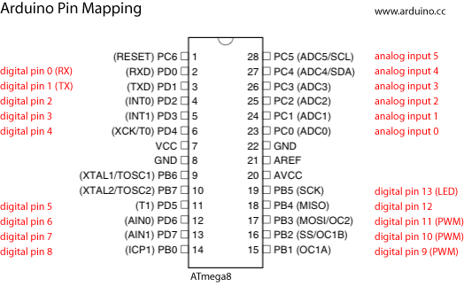 and we have :LiquidCrystal lcd(8, 7, 5, 4, 16, 2) I confused sorry.:-( |
|
|
|
|
09/15/2010, 10:03 AM
|
#141 |
|
Team RC Member
Join Date: Sep 2003
Location: NY
Posts: 17,749
|
I switched the pins for the standard LiquidCrystal around quite a bit, because I "needed" the default pins for other purposes. In a design where you need every single I/O pin, you need to choose carefully which pin you use for what based on the hardware capabilities (i.e. PWM pins, etc.)
__________________
Inconveniencing marine life since 1992 "It is my personal belief that reef aquaria should be thriving communities of biodiversity, representative of their wild counterparts, and not merely collections of pretty specimens growing on tidy clean rock shelves covered in purple coralline algae." (Eric Borneman) |
|
|
|
|
09/21/2010, 10:28 AM
|
#142 |
|
Registered Member
Join Date: Sep 2010
Posts: 6
|
Next step
So is the next step in pursuing this project on our own getting the PCB made? Can I assume that there will be others interested and that if fabrication involves a minimum of 10 units then there might be interest in a group buy/share? $40 per 10cm x 10cm PCB was mentioned in a previous post (I don't know how large the final board is) so if the reference is anywhere near that $40 is plenty reasonable but it seems silly to just keep the extras.
Or am I completely misunderstanding the whole process? |
|
|
|
|
09/21/2010, 10:42 AM
|
#143 |
|
Team RC Member
Join Date: Sep 2003
Location: NY
Posts: 17,749
|
Yes, I am releasing the design - you basically need to get your hands on a PCB. Besides ordering in batches, there are a few shops that will make just one or two pcbs (batchpcb.com, or dorkbotpdx).
It's still worth mentioning that while I've tested this myself, there may be changes over time, and as I (or others) implement those changes, there will likely be "leftover" PCBs, so if you're willing to wait, that might be the best way to get a pcb for cheap. It's also worth mentioning that reefcentral has fairly strict "group buy" policies, so if folks want to go in that direction, it might be best to take the discussion offline or elsewhere.
__________________
Inconveniencing marine life since 1992 "It is my personal belief that reef aquaria should be thriving communities of biodiversity, representative of their wild counterparts, and not merely collections of pretty specimens growing on tidy clean rock shelves covered in purple coralline algae." (Eric Borneman) |
|
|
|
|
09/21/2010, 07:21 PM
|
#144 |
|
Registered Member
Join Date: Sep 2008
Location: Minnesota
Posts: 69
|
I am VERY excited about this thread. I wasted so much time today trying to figure it out for myself! I was going to do a USB to RF then RF LED dimmer. I'd much prefer not leaving my computer on all the time! Thanks for your hard work! I'm looking forward to updates!
|
|
|
|
|
09/21/2010, 08:58 PM
|
#145 | |
|
Premium Member
Join Date: Feb 2001
Location: Park Ridge
Posts: 2,232
|
Quote:
I got eagle but no files has something changed on the link? A direct link to the files would help. Here on this forum I'm used to Direcdt Links, Pics, and YouTube. I have several ELN 60-48D but the control build is less than user friendly. AKA No Go DWZM To do your build you have road blocks...Please remove them. Bill
__________________
NKAWTG Current Tank Info: 570 Soft/LPS, 330SPS & 440 refug |
|
|
|
|
|
09/21/2010, 09:15 PM
|
#146 | |
|
Registered Member
Join Date: Jun 2007
Location: Waterford, MI
Posts: 790
|
Quote:
I dont have eagle so Im not sure if Im looking at what you need, or if you need more than what's there.. |
|
|
|
|
|
09/21/2010, 09:34 PM
|
#147 | |
|
Premium Member
Join Date: Feb 2001
Location: Park Ridge
Posts: 2,232
|
Quote:
This is seriously un-user friendly I have eagle but dont know what to do with it...DWZM Please make this easy. Bill
__________________
NKAWTG Current Tank Info: 570 Soft/LPS, 330SPS & 440 refug |
|
|
|
|
|
09/21/2010, 09:51 PM
|
#148 |
|
Registered Member
Join Date: Jun 2007
Location: Waterford, MI
Posts: 790
|
health care stuff??? here's a link to the raw pde firmware file.
http://typhon-reef.googlecode.com/sv...hon/typhon.pde you're going to also need to download and include the libraries listed in the comments section shown below: the raw pde file should contain something starting with: /* // Typhon firmware // v0.1 alpha 2010-08-06 // N. Enders // // This sketch provides firmware for the Typhon LED controller. // It provides a structure to fade 4 independent channels of LED lighting // on and off each day, to simulate sunrise and sunset. // // Current work in progress: // - store all LED variables in EEPROM so they are not reset by a loss of power // // Future developments may include: // - moon phase simulation // - storm simulation // // Sketch developed in Arduino-18 // Requires LiquidCrystal, Wire, EEPROM, EEPROMVar, and Button libraries. // Button is available here: http://www.arduino.cc/playground/Code/Button // EEPROMVar is available here: http://www.arduino.cc/playground/upl...PROMVar_01.zip */ even with this and the arduino software it's not totally intuitive but hey, DIY is about learning isnt it? edit: oh wait if you're playing in eagle, that's for the hardware only.. my bad. Last edited by XSiVE; 09/21/2010 at 10:24 PM. |
|
|
|
|
09/21/2010, 10:38 PM
|
#149 |
|
Premium Member
Join Date: Feb 2001
Location: Park Ridge
Posts: 2,232
|
Thanks
Will give it a try tomorrow as its late. Bill
__________________
NKAWTG Current Tank Info: 570 Soft/LPS, 330SPS & 440 refug |
|
|
|
|
09/22/2010, 07:24 AM
|
#150 | |
|
Team RC Member
Join Date: Sep 2003
Location: NY
Posts: 17,749
|
The files are in an svn repository, which is a tool developers use to version software and other electronic files while they are under development (again, I'll remind people that this is currently very much a development effort, and won't be presented in an "easy to swallow" format until it's stable and I feel it's ready for that. While it is a working, functioning device at this point that will dim your LEDs, the project isn't at a stage where I've put any effort into making it easy to swallow yet, since it still may change over the next few weeks/months). It's not really standard practice to direct-link files in svn repositories, because it kind of defeats half the purpose of versioning the files in the first place. I'm sorry if this is awkward or difficult for people, but this is the method I've chosen to develop this project (in my spare time, as an open source effort, with no hopes or plans to be compensated).
Once the project reaches a "finished" major-version state, I'll post the final, stable documents in the "downloads" section of the google code site, and they'll be easier to find, and directly-linkable. I'm also planning on posting a quick FAQ and a user manual once we reach that point. This is essentially the intended use of the google code framework - develop in the repo tab, release stable versions in the download tab. In the meantime, this is the best I can do. Click on this link: http://code.google.com/p/typhon-reef/source/browse/ You'll get the directory structure for the svn repository, in "browse" mode. It works like Windows Explorer. There's a tree structure of folders on the left, and lists of files are displayed on the right. The files you need are in svn/trunk/hardware/typhon and svn/trunk/software/typhon. To get to the files, first click on the word "trunk" in the tree on the left: 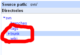 Then, click on the other folders to drill down to the directory you're looking for, for instance, trunk/hardware/typhon to get the hardware files: 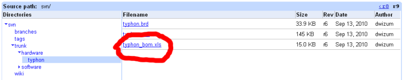 The expanded tree is on the left. The list of files is on the right. There are three hardware files: typhon.sch is the schematic; use Eagle to open it typhon.brd is the board file; use Eagle to open it typhon_bom.xls is the bill of materials; use Excel to open it When you click on the name of one of the files, you'll get to the change log page for that file. Click on the "view raw file" link on the right: 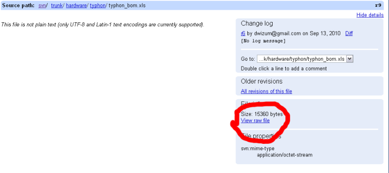 Your browser will download the file and/or attempt to open it, depending on your browser's configuration and which file you clicked on. Can't really help you there as it'll be dependent on your configuration. The current firmware (software) is an Arduino "sketch" (Arduino's name for a program file) located in the path specified above. It's a plain text file with a .pde extension. You can edit it with any text editor but the best practice is to get the Arduino IDE and open it with that, since you'll need that to upload it to your hardware (unless you want to build your own toolchain from scratch, in which case you probably aren't reading this post! )You'll also need a piece of hardware to convert the I/O capabilities of your computer to something the Typhon controller can understand, as detailed above: Quote:
__________________
Inconveniencing marine life since 1992 "It is my personal belief that reef aquaria should be thriving communities of biodiversity, representative of their wild counterparts, and not merely collections of pretty specimens growing on tidy clean rock shelves covered in purple coralline algae." (Eric Borneman) |
|
|
|
|
|
|
|
 Similar Threads
|
||||
| Thread | Thread Starter | Forum | Replies | Last Post |
| Cheap Moonlight | ticklesworth | New to the Hobby | 3 | 04/04/2010 04:09 PM |
| Cheap Moonlight | ticklesworth | Do It Yourself |
0 | 04/03/2010 08:52 AM |
| Arduino base controller - power pack ONLY TODAY | MaLi | Do It Yourself |
0 | 03/07/2010 05:56 AM |
| Sumps 101: Cheap, simple and effective for small tanks | cody6766 | Central Oklahoma Marine Aquarium Society | 8 | 01/06/2009 10:57 AM |


