
|
|
|
|||||||
 |
| Thread Tools |
 06/05/2016, 04:56 PM
|
#2301 |
|
100-mile-commuter
Join Date: Dec 2004
Location: almost nevada
Posts: 4,721
|
As an aside, does the controller/driver or the motor block tend to fail first in these pumps? If it's the motor block, are the windings/insulation/etc actually faulted or is it mechanical wear?
There are tons of ways to do things "good enough" but with higher failure chances or worse performance - even EcoTech pre-QD drivers were not very good, but it would help to know what needs the most improvement.
__________________
Custom electronics purveyor. blueAcro.com Current Tank Info: 90g SPS+mixed reef (10 yrs): LEDBrick LEDs, 40g custom sump, Ca reactor, chiller, Vortech, lots of custom electronics |

|

|
|
06/06/2016, 05:41 AM
|
#2302 |
|
Registered Member
Join Date: Jul 2011
Posts: 17
|
When connecting Jebao wave pumps, do I need to build a pwn circuit similar to that shown for the Fans in the schematic or does it work directly from the output from the Arduino.
|
|
|
|
|
06/06/2016, 06:56 AM
|
#2303 |
|
Registered Member
Join Date: Dec 2015
Location: Salem, OR
Posts: 56
|
Directly from the PWM pins on the Arduino.
Sent from my iPhone using Tapatalk |
|
|
|
|
06/06/2016, 08:30 AM
|
#2304 | |
|
Registered Member
Join Date: Mar 2008
Location: sf bay area
Posts: 5,165
|
Quote:
the other circuit is for rpm measurement and for turning off the fan power and are not needed for pump control. |
|
|
|
|
|
06/06/2016, 08:38 AM
|
#2305 | |
|
Registered Member
Join Date: Mar 2008
Location: sf bay area
Posts: 5,165
|
Quote:
 I'm sure the competition did some part in disseminating bad publicity. As I stated, I think the controller itself was pretty well designed. I'm sure the competition did some part in disseminating bad publicity. As I stated, I think the controller itself was pretty well designed.I do not recall reading about dcs or dct pump failures, only dc pump and the WP and RW pumps. and the dct pumps has been out since 2014, and dcs is essentially the same as dct pump. I just did a google search and only found one, and its a youtube video showing dct pump issue. And from the blinking light error code, it is a power supply error. I got the same blinking light if I use a 12v power supply on the controller. I just thought I'd try, since the icecap gyre interface is supposed to work even with 12v, but apparently, the stock pump controller does not (assuming gyre controller does not work with 12v as well). Last edited by d0ughb0y; 06/06/2016 at 08:55 AM. |
|
|
|
|
|
06/06/2016, 08:49 AM
|
#2306 |
|
Registered Member
Join Date: Mar 2008
Location: sf bay area
Posts: 5,165
|
I am searching for a single chip bldc motor controller, but it seems like everything out there requires hall sensors.
I did find an atmel avr application note on how to program the avr chip as a sensorless motor controller. It only requires the avr cpu, the FET drivers, and a bunch of resistor dividers for BEMF reading. I'll probably give this a try and see how it goes. I have to analyze/understand the code and convert it to arduino code. If it works, all the parts should not cost more than $20. bldc motor control is all new to me. The advantage of using arduino to control is, it should be a simple matter to add features like apex interface, backup battery detection (if input voltage falls from 24v to 12v). I think the avr sample code has code for detecting overcurrent and stalling. Last edited by d0ughb0y; 06/06/2016 at 09:01 AM. |
|
|
|
|
06/06/2016, 10:18 AM
|
#2307 |
|
100-mile-commuter
Join Date: Dec 2004
Location: almost nevada
Posts: 4,721
|
Some of the TI DRV chips can be set to run in an open loop mode without Hall effect sensors or FG trace inputs. It's not super obvious from the data sheet but it is in the mode setting section.
Digital SPI speed control is a nice way to avoid the need to write any realtime motor control code
__________________
Custom electronics purveyor. blueAcro.com Current Tank Info: 90g SPS+mixed reef (10 yrs): LEDBrick LEDs, 40g custom sump, Ca reactor, chiller, Vortech, lots of custom electronics |
|
|
|
|
06/06/2016, 10:45 AM
|
#2308 | |
|
Registered Member
Join Date: Mar 2008
Location: sf bay area
Posts: 5,165
|
Quote:
From what I understand reading the chip with SPI input datasheet, it is still the cpu that controls the commutation by sending commands to the motor controller chip via SPI. I am wondering if the use of LM339 comparator is to convert the BEMF to digital data that can be used for hall sensor input. If that is the case, then there will be more motor controller chip choices. The Atmel application note reads the BEMF resistor divider signal using analog input, and compares it to reference from motor power supply (24v) resistor divider. I think the function of the LM339 is the same, except the output is already digital. The chip used in jebao controller I'm pretty sure is a cpu or a cpu/motor controller combo, as the same chip drives the LEDs and input to push buttons. |
|
|
|
|
|
06/06/2016, 10:55 AM
|
#2309 |
|
100-mile-commuter
Join Date: Dec 2004
Location: almost nevada
Posts: 4,721
|
My Neptune Apex web interface compatible DIY reef controller
The 3 phase controller I was looking at featured an open loop mode: http://m.ti.com/product/drv8308
The Jebao is likely using an MCU for motor controller. There isn't anything wrong with this at all, it's just software to write And yes, the LM339 would act as the threshold detect, assuming the MCU used doesn't have ADCs (or reasonable ones). Mind linking the app note from Atmel?
__________________
Custom electronics purveyor. blueAcro.com Current Tank Info: 90g SPS+mixed reef (10 yrs): LEDBrick LEDs, 40g custom sump, Ca reactor, chiller, Vortech, lots of custom electronics |
|
|
|
|
06/06/2016, 11:31 AM
|
#2310 | |
|
Registered Member
Join Date: Mar 2008
Location: sf bay area
Posts: 5,165
|
Quote:
|
|
|
|
|
|
06/06/2016, 11:38 AM
|
#2311 | |
|
Registered Member
Join Date: Jul 2011
Posts: 17
|
Quote:
Sent from my SM-G935F using Tapatalk |
|
|
|
|
|
06/06/2016, 11:39 AM
|
#2312 | |
|
Registered Member
Join Date: Jul 2011
Posts: 17
|
Quote:
Sent from my SM-G935F using Tapatalk |
|
|
|
|
|
06/06/2016, 11:47 AM
|
#2313 | |
|
Registered Member
Join Date: Mar 2008
Location: sf bay area
Posts: 5,165
|
Quote:
I read the mode section. I think it is for speed control, and not for commutation? or are they one and the same? My understanding is, the pwm for speed control controls the voltage applied to the motor coil, so the higher the voltage the faster the motor will spin. The sensor (bemf or hall) tells the controller when to switch to the next commutation state. |
|
|
|
|
|
06/06/2016, 03:00 PM
|
#2314 |
|
Registered Member
Join Date: Jan 2009
Posts: 151
|
I'm looking to get one of these DCT pumps but would want to have my PLC control it via a 0-10v or 0-5V input signal like the waveline pumps or older Jabeo pumps. Is that even a possibility with these new controllers? It sounds to me like it wasn't at this point. Not sure if something can be developed to make it work using an analog input signal.
|
|
|
|
|
06/06/2016, 03:22 PM
|
#2315 | |
|
Registered Member
Join Date: Mar 2008
Location: sf bay area
Posts: 5,165
|
Quote:
You can always get the icecap gyre interface for $125 (probably can't handle pumps higher than 50watts). But that already costs more than the dct pump itself. I know 99% of people will readily fork over $125, but I think there has to be another option. |
|
|
|
|
|
06/07/2016, 04:26 AM
|
#2316 |
|
Registered Member
Join Date: May 2004
Location: Dallas, TX
Posts: 11,033
|
Still not sure of the benefit of creating a whole drive circuit vs hot-overriding the native controller's buttons.
The work and complexity is disproportionately more for a small range of additional control?
__________________
Failure isn't an option It's a requirement. 660g 380inwall+280smp/surge S/L/Soft/Maxima/RBTA/Clown/Chromis/Anthias/Tang/Mandarin/Jawfish/Goby/Wrasse/D'back. DIY 12' Skimmer ActuatedSurge ConcreteScape |
|
|
|
|
06/07/2016, 06:56 AM
|
#2317 | |
|
Registered Member
Join Date: Jan 2009
Posts: 151
|
Quote:
Would I be able to use what you are developing as standalone unit without an adrunio? That would be great. yea I'm not willing to fork over $125 for an interface. |
|
|
|
|
|
06/07/2016, 10:12 AM
|
#2318 | ||
|
Registered Member
Join Date: Mar 2008
Location: sf bay area
Posts: 5,165
|
Quote:
Quote:
What model pump are you using? |
||
|
|
|
|
06/07/2016, 10:46 AM
|
#2319 | |
|
Registered Member
Join Date: Jan 2009
Posts: 151
|
Quote:
|
|
|
|
|
|
06/07/2016, 02:08 PM
|
#2320 | |
|
Registered Member
Join Date: May 2004
Location: Dallas, TX
Posts: 11,033
|
Quote:
I'm all for finer control though... just that perfect is the enemy of the good.
__________________
Failure isn't an option It's a requirement. 660g 380inwall+280smp/surge S/L/Soft/Maxima/RBTA/Clown/Chromis/Anthias/Tang/Mandarin/Jawfish/Goby/Wrasse/D'back. DIY 12' Skimmer ActuatedSurge ConcreteScape |
|
|
|
|
|
06/07/2016, 02:42 PM
|
#2321 |
|
Registered Member
Join Date: Jul 2011
Posts: 17
|
Please find attached my contribution. I have quickly whipped up an Android application to display a webpage.
When you first load the app it will display a white screen. Simply tap immediately below the top status bar and the URL Setup page will appear. Enter the URL of you reef controller, including http://. If you can't get it to work simply enter http://www.google.com and followed by clicking the Save button. If all was entered correctly the google website should appear. To change the URL again, simply click below the status bar. The apk is called OneWebPage but the app name is Reef Controller. I have also included a Reef Cartoon Icon. Enjoy. https://www.dropbox.com/s/admnpfnhlz...bPage.apk?dl=0 |
|
|
|
|
06/07/2016, 03:22 PM
|
#2322 |
|
Registered Member
Join Date: Mar 2016
Posts: 1
|
My Neptune Apex web interface compatible DIY reef controller
Hi, I am new in this thread. What you did is perfect, the very best DIY controller! I have a problem while compiling with 1.6.7 ide arduino software"time_t was not declared in this scope". I have set up the libraries as from GitHub in libraries in sketch folder. Did someone know what's wrong?
Gesendet von iPhone mit Tapatalk Last edited by GeorgiosK; 06/07/2016 at 03:55 PM. |
|
|
|
|
06/08/2016, 01:09 AM
|
#2323 | |
|
Registered Member
Join Date: Mar 2008
Location: sf bay area
Posts: 5,165
|
Quote:
try arduino 1.6.5 if you are not able to get it to work on 1.6.7. |
|
|
|
|
|
06/08/2016, 01:44 AM
|
#2324 |
|
Registered Member
Join Date: Mar 2008
Location: sf bay area
Posts: 5,165
|
Got the commutation signals working. I only have the arduino on a breadboard and no driver circuit yet, so I hard coded some values to get the state machine going.
The motor signal period is 24ms, and each high pulse is 8ms. The bottom channel is the 20khz pwm for speed control. According to the Atmel notes, it should be ANDed with the 6 motor signals. The stock controller only applies the speed pwm to the lower signals only, so I will do the same. The motor startup runs 8 commutation steps using hard coded timing, I don't think that is even 1 revolution, then assumes there is BEMF signal by that time and hands off to BEMF controlled commutation. The gap between the startup sequence and the BEMF controlled commutation should not be that big. The code uses timer0 to auto trigger adc reading, but since timer0 is used by arduino for millis() function, I switched it to use timer2 but left the auto trigger on timer0 which is slower. I want to avoid modifying the millis() function code to use timer2, but I may have to do that. If I am able to get some MOSFETs, I can wire something up and test this weekend. I'll probably capture the startup sequence timing of the stock controller and tweak the program to make the startup as similar as possible to the stock controller. 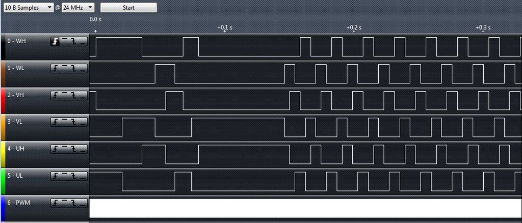
Last edited by d0ughb0y; 08/05/2017 at 08:59 PM. |
|
|
|
|
06/08/2016, 04:39 AM
|
#2325 |
|
Registered Member
Join Date: May 2004
Location: Dallas, TX
Posts: 11,033
|
what data capture device are you using? A USB oscilloscope?
__________________
Failure isn't an option It's a requirement. 660g 380inwall+280smp/surge S/L/Soft/Maxima/RBTA/Clown/Chromis/Anthias/Tang/Mandarin/Jawfish/Goby/Wrasse/D'back. DIY 12' Skimmer ActuatedSurge ConcreteScape |
|
|
|
|
| Thread Tools | |
|
|


