
|
|
 06/23/2018, 06:47 PM
|
#1 |
|
Registered Member
Join Date: Jun 2004
Location: Arlington, VA
Posts: 743
|
Critique my steel stand design (Enineers?)
Happy Saturday!
I picked up a 180g acrylic tank that I've been cleaning up and need to get a stand for it. The sump is the same width as the tank (24"), so I am going with steel to be able to fit it. Below is what I have designed. Based on this steel deflection calculator (http://metalgeek.com/static/deflection.php), the top beam would have a deflection of just under .1" using 2" x .125" steel tubing. 1.5" x .125" would have a deflection of .25". This assumes a load of 2500 lbs (going over for safety). This also assumes I am using the calculator correctly. The corner posts all have gussets for shear bracing. Will this stand be sufficient to support my 180 long term? I appreciate any and all feedback. Thank you in advance and sorry for the poor drawing. 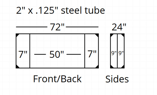 180g Steel Stand by Mike Burns, on Flickr 180g Steel Stand by Mike Burns, on Flickr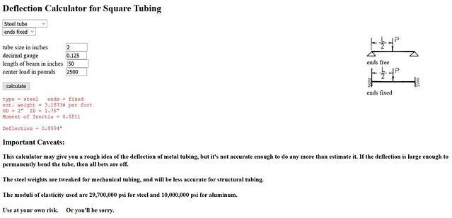 Deflection Calculator by Mike Burns, on Flickr Deflection Calculator by Mike Burns, on Flickr
|

|

|
|
06/23/2018, 07:35 PM
|
#2 |
|
Registered Member
Join Date: Nov 2001
Location: Upstate South Carolina
Posts: 478
|
Quick comments:
- There are two horizontal beams supporting the tank, so each beam will only take half the weight of the tank. - The tank is a distributed load, not a point load in the center, so you need this formula https://www.engineersedge.com/beam_b...m_bending1.htm. I will refrain from giving any more specific advice because I don't have enough relevant experience. Steve |
|
|
|
|
06/23/2018, 08:15 PM
|
#3 |
|
Registered Member
Join Date: Jun 2004
Location: Arlington, VA
Posts: 743
|
Thank you Steve. My understanding is that Deflection = (P x L^3) / (192 x E x I), where P = load in lbs, L = length in inches, E = modulus of elasticity, and I = moment of inertia. I'm using .55 as the moment of inertia for 2" x .125" steel tubing.
Now, if I use the following values: P = 651 (If I divide 2500 by the total length of the four top rails (72+72+24+24) I get 13. When I multiply 13 by 50", I get 651.) L = 50" (This is the largest span between two vertical posts.) E = 29,000,000 I = .55 I get a deflection of .03". Hopefully someone can come in here and tell me my equations and math are all wrong and how to do it correctly 
Last edited by clownfish4; 06/23/2018 at 08:43 PM. |
|
|
|
|
06/24/2018, 04:40 AM
|
#4 |
|
Registered Member
Join Date: Feb 2011
Location: Cypress, Texas
Posts: 1,904
|
That weight assumption seems sketchy (P)... With that shape of stand i would just omit the ends (7" x 24" rectangles) and treat it as a 50" x 24" stand, with a load of roughly 20% less.
With the two beams i calculate with the above about .100" of deflection in the center. Personally i don't care for square tube, rectangle is a better beam. 1" x 3" 11 gauge tubes nearly double the 2" square 11 gauge in performance (I = 0.918444 vs I = 0.53374). 1" x 3" tubes stitched together into 2" x 3" beams would be pretty darn stout (I ~ 2.4). Even 2" x 3" 11 gauge tubes would be a huge upgrade from 2" square (I = 1.4164). With acrylic tanks you will also need plenty of cross members and such to cut up the bottom plane, so a third beam splitting the 24" in half wouldn't hurt. |
|
|
|
|
06/24/2018, 06:37 AM
|
#5 |
|
Registered Member
Join Date: Sep 2003
Location: North Carolina
Posts: 20,050
|
Me... I'd remove the center upright on the sides as its just adding weight and not needed at all.. I'd also just have one center upright in the front and back (and not have those 2 @ 7" ones) and slid the sump in from the side..
It is more than sufficient like that.. My old 120G (6ft tank) stand was like that but with 1" tube. And yes that deflection calculator is not applicable here..
__________________
Who me? |
|
|
|
|
06/24/2018, 07:33 AM
|
#6 |
|
Registered Member
Join Date: Jun 2004
Location: Arlington, VA
Posts: 743
|
Thank you Gorgok. I guess the new question is what amount of deflection is acceptable? I have to assume that 2 1x3s bound together would effectively double the cost of the stand
 For a 1x3" 11 gauge, the moment of inertia is ~.9 on the long side, but only ~.1 on the short side. A 2x2" 11 gauge would be ~.5 on both sides. Is there any reason to be concerned about a low value on the short side? Doh, I completely forgot to add a top view. My plan was to put 3 cross beams, top and bottom. So with the 2 ends, 5 total, putting one every 1.5'. mcgyvr - That's not possible. My sump is the same width as the tank, 24", so it will be sitting on the bottom rails. It can't slide in from the side as it won't fit between the corner posts. |
|
|
|
|
06/24/2018, 10:35 AM
|
#7 | |
|
Registered Member
Join Date: Nov 2001
Location: Upstate South Carolina
Posts: 478
|
Quote:
Gorgok's comment about rectangular tube being better are spot on, as long as the wider dimension is vertical. You might consider 1.5"x3" tube for the long spans with 1.5" square for the legs. You could also consider a third 72" span under the tank. It seems to me it would be more efficient to use a conventional stand and a new sump, unless you are really attached to the sump for some reason. Steve |
|
|
|
|
|
06/24/2018, 11:26 AM
|
#8 |
|
Registered Member
Join Date: Jun 2004
Location: Arlington, VA
Posts: 743
|
Thank you Steve. The 1.5"x3" is intriguing. Looks like that would give an I of ~1 x ~.4. The primary reason I want to keep the sump is cost. The size/layout are great and I got it for so cheap I'll save money by spending a little more on the stand.
One other thing I've been thinking about is the counter force on the other side of the two vertical posts. The equation does not account for the downward force on ~30% of the surface area on the beams. With the post, wouldn't that force counter act downward deflection between the posts? I think it still comes back to what level of deflection is acceptable though. <.1" seems pretty low to me, but I'm not sure what the risk factor is at .05, .1, .2, etc. Also, do you see any benefit in a third 72” beam vs 3 cross beams? Last edited by clownfish4; 06/24/2018 at 11:32 AM. |
|
|
|
|
06/24/2018, 01:44 PM
|
#9 | |
|
Registered Member
Join Date: Oct 2007
Location: West Michigan
Posts: 1,010
|
couldn't you have flanges welded to the center supports and just bolt them into place after you put the sump in?
Quote:
I'd suspect 1sq tube would be sufficient spaced on 16". likely a lighter gauge would be fine too. Last edited by on the spot; 06/24/2018 at 01:49 PM. |
|
|
|
|
|
06/24/2018, 01:57 PM
|
#10 | ||
|
Registered Member
Join Date: Jun 2004
Location: Arlington, VA
Posts: 743
|
Quote:
Quote:
|
||
|
|
|
|
06/24/2018, 08:06 PM
|
#11 |
|
Registered Member
Join Date: Feb 2011
Location: Cypress, Texas
Posts: 1,904
|
With acrylic you need to chop up the bottom plank quite a bit or use something pretty darn stout by itself as the bottom 'plank' (like a stone top). I wouldn't do 16" x 24" on center framing personally, since steel is relatively cheap compared to the tank, and you can (as above) down size, down gauge or even use angle iron the cross braces to chuck in more.
I would put in the center rail and then space out cross members to come down to about 12" x 12" on center framing just because. With that much steel you can pretty much put whatever 'planking' you want, even thin ply. If you ground the steel really smooth probably nothing would be fine too at that point, but acrylic is slippery on steel and that would bother me. I probably overbuild, but then again nothing fails.... |
|
|
|
|
06/24/2018, 08:16 PM
|
#12 | ||
|
Registered Member
Join Date: Oct 2007
Location: West Michigan
Posts: 1,010
|
Quote:
Quote:
|
||
|
|
|
|
06/24/2018, 08:36 PM
|
#13 | |
|
Registered Member
Join Date: Nov 2001
Location: Upstate South Carolina
Posts: 478
|
Quote:
I will offer an estimate below, just to give some idea as to how you might approach this - but warn anyone reading that you take 100% risk in your own design - this IS NOT a design recommendation (and quite frankly, 0.1" deflection would scare me): - Consider a scenario where the center span deflects by 0.1". The bottom of the tank deflects to match, and pulls the side walls down via the edges. The side walls now take load and can be considered as beams using the same equations above. For convenience, I went back to a calculator that assumes a point load (https://www.engineering.com/calculators/beams.htm), which indicates that a polycarbonate sheet (50" x 24" x 0.5") will deflect 0.1" under a load of about 460 pounds with a stress of ~480 PSI (polycarbonate and acrylic have reasonably similar modulus). So in this rough estimate the acrylic panels support ~960 lb of load via the two sidewalls while the underlying steel beams must take the remaining ~1540 lb with 0.1" deflection. More importantly, this gives a stress level that can be compared to a presumed safe limit for the acrylic. Steve Last edited by Turtlesteve; 06/24/2018 at 09:26 PM. |
|
|
|
|
|
06/25/2018, 04:48 PM
|
#14 |
|
Registered Member
Join Date: Jun 2004
Location: Arlington, VA
Posts: 743
|
Gorgok, If I had an unlimited budget or was a skilled welder I'd be all for that! As it stands, I'm looking more so to what is structurally sound vs super excessive. I'll plank with whatever I need to, probably dual 3/4" ply.
Thank you on the spot, I misunderstood your comment at first. Thank you Steve. Would you forgo all cross beams for the third middle beam? I would also add two additional legs on either side of the 50" mark for the middle beam. Worst comes to worst I may also just get some cinder blocks and dual 3/4" ply since I'm just in a basement and not concerned with aesthetics or height until I move, haha. Be a lot easier and cheaper for the time being. |
|
|
|
|
06/25/2018, 06:08 PM
|
#15 |
|
Registered Member
Join Date: Nov 2001
Location: Upstate South Carolina
Posts: 478
|
If it were me, I'd still use short cross beams to link the long ones.
However if you are really asking what I'd do, the first change I'd make is to use wood. You could achieve less deflection, less cost, and a simpler build. An example load table is linked below. http://www.southernpine.com/app/uploads/AL_21-26L.pdf |
|
|
|
|
06/25/2018, 06:13 PM
|
#16 |
|
Registered Member
Join Date: Jun 2004
Location: Arlington, VA
Posts: 743
|
Thank you Steve. I was avoiding wood because I didn’t think I could get a 50” span. But if I can, I’ll absolutely go with wood. I’ll do more research on that.
|
|
|
|
|
06/25/2018, 06:45 PM
|
#17 |
|
Registered Member
Join Date: May 2013
Posts: 506
|
I have little experience in this beyond what I know from modeling bridges. If you want less deflection then increase the chord of the beam, hence the suggestion for a 1.5 x 3 with the 3 inch side on the vertical. Generally speaking, doubling the chord height triples the load capacity.
|
|
|
|
|
06/26/2018, 02:30 PM
|
#18 |
|
Registered Member
Join Date: Jun 2004
Location: Arlington, VA
Posts: 743
|
Hmm, so from what I can tell a pine 2x8 has an E between 1,000,000 and 1,500,000 with an I of 47.6. If that is correct, using the lower E of 1,000,000, the deflection on a single 50 inch beam under 2500 lbs would be .03. Two beams would be .02 and three beams would be .01. Does that sound correct?
Based on the above, I think a stand built with 3 2x8 pine beams would be more than sufficient, using 4 corner posts and 4 posts 50" apart. With three beams I shouldn't even need the 50" spaced posts, but for the sake of overbuilding I would use them. Thoughts? I also need to decide what size I would use for the vertical supports. It seems like 2x4s should be sufficient, but I would probably feel better with 2x6 or 2x8. (E and I source - https://books.google.com/books?id=X3...page&q&f=false) |
|
|
|
|
06/26/2018, 04:54 PM
|
#19 |
|
Registered Member
Join Date: Feb 2011
Location: Cypress, Texas
Posts: 1,904
|
For wood posts, i would go for whatever size is enough to support both the long and short rails (about half for each) at the same time. So for a single rail in both directions a 2 x 4 is plenty, for a doubled up long rail and single short one a 2 x 6 is plenty.
No idea on the deflection numbers for wood though. |
|
|
|
|
06/26/2018, 05:09 PM
|
#20 |
|
Registered Member
Join Date: Jun 2004
Location: Arlington, VA
Posts: 743
|
Thank you Gorgok, I guess the 2x4 shouldn’t bother me since the force is applied down the length, vs on it. I’m going to try and cad the stand, but what I am thinking is 3 2x8s for top and bottom frames, twelve 2x4 posts (4 per corner and 6 for the 50” gap), and however many cross posts I can make out of the leftover 2x8. With 8’ boards I should have enough leftover for twelve ~12” cross boards. If I put all 12 up top, that should make each gap roughly 12”x12”. I’d have to buy another board to do cross sections under the sump, or use less on the top.
Do you think 2 3/4” plywood boards stacked is overkill for the top? |
|
|
|
|
06/26/2018, 06:42 PM
|
#21 |
|
Registered Member
Join Date: Nov 2001
Location: Upstate South Carolina
Posts: 478
|
I like where you're going. It might be advantageous to use 2x6's (and just use more of them to get the same deflection) depending on how tall the sump is.
Overkill is always better than having issues in the future. Steve |
|
|
|
|
06/26/2018, 07:43 PM
|
#22 |
|
Registered Member
Join Date: Jun 2004
Location: Arlington, VA
Posts: 743
|
I ran my design by RocketEngineer and he said a frame with 2 2x8 beams and only 2x4 corner posts is more than enough to support the weight of a 180. I've slimmed things down a bit. Please disregard the minor perspective issues, the design program I used isn't great. The bottom frame will be identical to the top, I just didn't put in the bottom cross beams in the drawing. The top and bottom will be a 2x8 box frame with 4 cross beams. The corners will each have two 2x4 posts. There will be an additional 4 posts on the 50" gap to provide an attachment point for doors. The top will likely be two 3/4" plywood tops glued together, still confirming that portion. I will likely skin with 1/4" plywood and will probably build surfaces and/or shelves in the two outer sections for Apex mounting and storage.
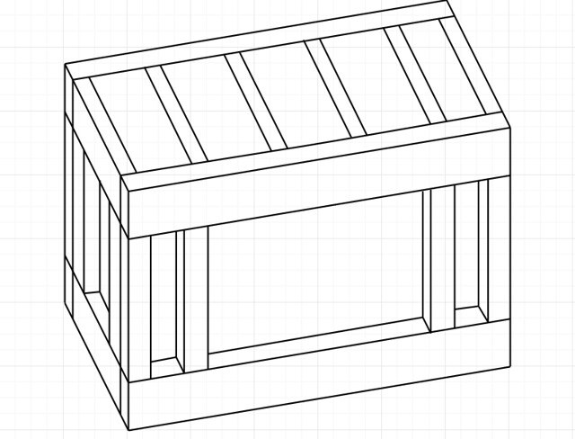 180 Stand Design by Mike Burns, on Flickr 180 Stand Design by Mike Burns, on Flickr
|
|
|
|
|
06/26/2018, 08:37 PM
|
#23 |
|
Registered Member
Join Date: Feb 2011
Location: Cypress, Texas
Posts: 1,904
|
You could downsize the bottom rails quite a bit without any issues. Only the parts with posts on them carry any load, minus the sump, but even then the floor carries that basically directly. Having more vertical room above the sump will be nice too.
|
|
|
|
|
06/27/2018, 01:50 PM
|
#24 |
|
Registered Member
Join Date: Jun 2004
Location: Arlington, VA
Posts: 743
|
Luckily AutoCad has a 30 day free trial! Below is the updated design. The top frame is 2x8s, everything else is 2x4s. The top will have two bonded 3/4" plywood tops. The sump will only have ~40 gallons in use, closer to 90 if the power goes out, so I'll use a single 3/4" ply top there. The design/dimensions listed do not include the plywood. All dimensions are in inches.
Thoughts? 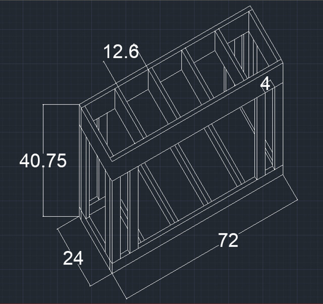 180g Stand by Mike Burns, on Flickr 180g Stand by Mike Burns, on Flickr
|
|
|
|
|
06/27/2018, 05:14 PM
|
#25 |
|
Registered Member
Join Date: Jun 2004
Location: Arlington, VA
Posts: 743
|
Here's a variation with 2x8 posts. This gets rid of the 4 extra posts and opens the area under the stand to 57.5". In the previous version there was only a 4" gap between posts, which is essentially unusable. This gives a much more workable space.
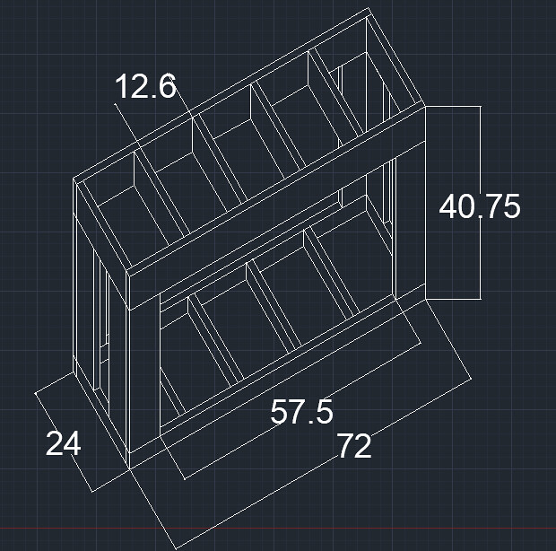 180g Stand 2 by Mike Burns, on Flickr 180g Stand 2 by Mike Burns, on Flickr
Last edited by clownfish4; 06/27/2018 at 05:22 PM. |
|
|
|
 |
|
|


