
|
|
 11/24/2008, 07:51 PM
|
#1 |
|
Premium Member
 Join Date: Jun 2006
Location: New columbia, PA
Posts: 137
|
koralia controller
somebody did look already how this 12V pump koralia are working ? Is it voltage variation of frequency ?
It's look like the controller is too much expensive ... Maybe it will be interesting to do a diy one, no ? I am electronic engineer and ready to have informations about it to make one ! |

|

|
|
11/29/2008, 02:50 PM
|
#2 |
|
Moved On
Join Date: Aug 2006
Location: Clearwater,Fl
Posts: 2,915
|
^
|
|
|
|
|
11/29/2008, 03:03 PM
|
#3 |
|
Registered Member

Join Date: Feb 2008
Location: New Jersey
Posts: 8
|
I looked at it on a scope. They are feeding the pump 15v AC square wave. Low speed is at 30hz and high speed is at 60hz. The wave maker doesnt stop the pump, it drops it to an adjustable low speed then spins it up to an adjustable high speed. The timing is also adjustable.
|
|
|
|
|
11/29/2008, 05:17 PM
|
#4 |
|
Moved On
Join Date: Aug 2007
Location: Liverpool, NY
Posts: 1,461
|
Thanks for the info
does it stay 15 v and only the frequency varies? |
|
|
|
|
11/29/2008, 06:51 PM
|
#5 |
|
Registered Member
Join Date: Feb 2008
Location: New Jersey
Posts: 8
|
Voltage did NOT change, only the frequency. I will note there were some terrible harmonics.
|
|
|
|
|
11/29/2008, 06:56 PM
|
#6 |
|
Premium Member
Join Date: Jun 2006
Location: New columbia, PA
Posts: 137
|
ok, so we can play with a PWM ... somebody knows about the Current though the pump ? I guess, that should be about 2 Ampere. I can understand the price a little bit because to feed 4 pump, we need a pretty good transformer. The transformer will not be a little VA.
Somebody did open already the wavemaker ? |
|
|
|
|
11/29/2008, 07:12 PM
|
#7 |
|
Registered Member
Join Date: Feb 2008
Location: New Jersey
Posts: 8
|
The K4 12v is rated for 14w on high.
So 12vac RMS (re:30v ptp) @14w with 30hz-60hz square wave |
|
|
|
|
11/29/2008, 07:41 PM
|
#8 |
|
Moved On
Join Date: Aug 2007
Location: Liverpool, NY
Posts: 1,461
|
so a simple PWM and a MOSFET or switching transistor
should be pretty simple to build |
|
|
|
|
11/29/2008, 07:45 PM
|
#9 |
|
Registered Member
Join Date: Feb 2008
Location: New Jersey
Posts: 8
|
Its not DC...its AC.....so you'll need to drive an inverter from the pwm
You could drive a pair of FET's in an N and P configuration. Last edited by stcreef; 11/29/2008 at 08:12 PM. |
|
|
|
|
11/29/2008, 09:13 PM
|
#10 |
|
Premium Member
Join Date: Jun 2006
Location: New columbia, PA
Posts: 137
|
ok, I did tonight a prototype. I did simulate with a resistor (just 500mA right now). Do somebody have a cheap pump to sell ?
|
|
|
|
|
11/29/2008, 10:44 PM
|
#11 |
|
Premium Member
Join Date: May 2004
Location: Longmont, Co
Posts: 4,566
|
stcreef,
"Its not DC...its AC.....so you'll need to drive an inverter from the pwm You could drive a pair of FET's in an N and P configuration." EXACTLY! You would need to use a PWM to drive a H-bridge. Then you could recreate the AC waveform. The current has to flow both ways. The PWM/H-bridge has to approximate a Sinusoid to drive the pump. Once you get it to work at all, THEN you can vary the frequency to change speed. OTCHU, "ok, I did tonight a prototype. I did simulate with a resistor " Sounds like you are trying to simulate a DC load using PWM. Your computer fan can be controlled this way, not a synchronous AC motor. Stu
__________________
Some people think that I have Attention Deficit Disorder. They just dont understand that........ Hey! Look a chicken! Well, We KNOW GOD exists, but for US to exist without a GOD is preposterous .Umm wait a minute . Sounds a bit circular to me Current Tank Info: 125 Gal. display w/80 gal mud/caulerpa sump. Basement sump w/ LED Grow Light,Gravity fed Reeflo200 skimmer w/ ORCA Recirc, DIY calc reactor & kalk stirrer. Inline plumbed 75 Gal frag/settling tank. |
|
|
|
|
11/30/2008, 12:52 AM
|
#12 |
|
Registered Member
Join Date: Sep 2007
Posts: 24
|
Hey stcreef, I have a few questions.
When you put it on a scope, did you see a 50% duty cycle square wave for both 30hz and 60hz? I've never heard of an induction or synchronous motor being driven from a square wave 50% duty cycle efficiently. The harmonics are probably from the carrier pwm signal as well. Have you tried putting it through a low pass filter @ 60+hz? If they are using sine pwm signal, you'll never see the magnitude of the squave wave change. Even if the magnitude is at 15v, the sine output can still change from 0-12v. If you just vary the frequency and not the voltage, the motor's torque curve will be altered, not a good thing. Were you able to check the phase between the 2 lines as well? They might be 90 or 180 degrees apart, I'm not sure o.o Sorry for the many questions. I'm trying to figure out what kind of motor they use exactly. I'm in the process of trying to control these and have a dsp running the signals already. |
|
|
|
|
11/30/2008, 02:15 AM
|
#13 |
|
100-mile-commuter
Join Date: Dec 2004
Location: almost nevada
Posts: 4,721
|
Ouch, motor control with a square wave?
I should hook up my scope to my (radically overpriced) Tunze controller box.
__________________
Custom electronics purveyor. blueAcro.com Current Tank Info: 90g SPS+mixed reef (10 yrs): LEDBrick LEDs, 40g custom sump, Ca reactor, chiller, Vortech, lots of custom electronics |
|
|
|
|
11/30/2008, 09:11 AM
|
#14 | |
|
Registered Member
Join Date: Feb 2008
Location: New Jersey
Posts: 8
|
Quote:
 I specifically looked for phasing and did not see a difference in phase. As a side note, I will tell you that these pumps do NOT have enough power to be used in a wavebox. How do I know? Simple, I tried it. 1400gph just isnt enough to overcome the aperture incoming pressure. You may be able to over drive them, but my suspicions are that it would compromise the pumps longevity. The pumps themselves are comparatively inexpensive ~$65 for the K4 12v. |
|
|
|
|
|
11/30/2008, 10:56 AM
|
#15 |
|
Premium Member
Join Date: Jun 2006
Location: New columbia, PA
Posts: 137
|
Stu,
No I did a AC -15 + 15V square signal . I did use just a resistor right now because I don't have a pump. I am going to buy one and check if everything is fine. |
|
|
|
|
11/30/2008, 11:08 AM
|
#16 |
|
Premium Member
Join Date: Jun 2006
Location: New columbia, PA
Posts: 137
|
Stu,
No I did a AC -15 + 15V square signal . I did use just a resistor right now because I don't have a pump. I am going to buy one and check if everything is fine. |
|
|
|
|
11/30/2008, 01:32 PM
|
#17 |
|
Registered Member
Join Date: Sep 2007
Posts: 24
|
Thanks for the answers stcreef. I'm glad somebody used an oscilloscope on one of these. ^^
|
|
|
|
|
11/30/2008, 01:58 PM
|
#18 |
|
Premium Member
Join Date: May 2004
Location: Longmont, Co
Posts: 4,566
|
Chances are that when you apply your "square wave" to the inductor of the motor, it will smooth out and look more like sinusoids.
It depends on the impedance of your power supply, the inductance of the motor you are driving, & the frequency you are trying to drive at. Stu
__________________
Some people think that I have Attention Deficit Disorder. They just dont understand that........ Hey! Look a chicken! Well, We KNOW GOD exists, but for US to exist without a GOD is preposterous .Umm wait a minute . Sounds a bit circular to me Current Tank Info: 125 Gal. display w/80 gal mud/caulerpa sump. Basement sump w/ LED Grow Light,Gravity fed Reeflo200 skimmer w/ ORCA Recirc, DIY calc reactor & kalk stirrer. Inline plumbed 75 Gal frag/settling tank. |
|
|
|
|
12/07/2008, 02:02 AM
|
#19 |
|
Registered Member
Join Date: Feb 2006
Posts: 1
|
The power supply company produces Meanwell, and this is exactly the model PPS200-12: http://www.meanwell.com/search/PPS-200/default.htm
[IMG]http://i33.*******.com/2mww378.jpg[/IMG] |
|
|
|
|
12/07/2008, 04:13 AM
|
#20 |
|
Moved On
Join Date: Aug 2006
Location: Clearwater,Fl
Posts: 2,915
|
This stuff is way above my lil cranium, but I'm hoping you guys figure something out at a decent cost. Then I can make my old man build me one. Are we getting closer to being able to do this?
|
|
|
|
|
12/07/2008, 09:30 AM
|
#21 |
|
Moved On
Join Date: Aug 2007
Location: Liverpool, NY
Posts: 1,461
|
I was thinking about building one of these but
since I have a pair of Tunze I'm feeling lazy  Though, I may build one for a grow out tank. I wish you luck in getting it sorted out, next will be to come up with a way to interface it with the various controllers. |
|
|
|
|
12/07/2008, 09:36 AM
|
#22 | |
|
Moved On
Join Date: Aug 2007
Location: Liverpool, NY
Posts: 1,461
|
Quote:
with my Profilux controller, by sending it a 3-8 vdc signal 8 volts is Max, 2.5 is mininum (profilux says to use 3 v) (I found that they turn off below 2.4) Tunze Pinout: Pin 1 : Control Voltage (3-8vdc) Pin 2 : - VGD (Ground) Pin 3 : Pin 4 : Pin 5 : + VDC |
|
|
|
|
|
12/07/2008, 02:44 PM
|
#23 |
|
Registered Member
Join Date: Sep 2007
Posts: 24
|
Hey franek, thanks for the shot!
You can definitely see they're using an mcu/dsp. Possibly a jtag port between the pots. You can see 8 mosfets grouped into 4 near the top of the pic. 4 mosfets makes a half bridge inverter to control 1 motor. I think this is definitely an AC motor controller using PWM. |
|
|
|
|
03/25/2014, 12:39 PM
|
#24 | ||||
|
Registered Member
Join Date: May 2012
Location: Indiana
Posts: 23
|
Quote:
Sounds like maybe this could be improved on by using 12Vrms AC > 17Vp = 34Vpp DC > AC inverter using an h-bridge and pwm carrier frequency to approximate a sine wave at 30-60 Hz, instead of using a plain square wave at 30-60 Hz. Basically something like this: 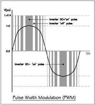 http://www.frequencyinverters.org/im...verter-pwm.jpg http://www.frequencyinverters.org/wh...er-106779.html First half of the wave: The duty cycle (D) of the pwm will start low, with h-bridge configured so the voltage across the motor alternates between 0V and 17V. Then D will increase to simulate the positive peak of a sine wave, then D will decrease towards 0 to simulate the sine wave lowering to cross 0V. Second half of the wave: Then the h-bridge will be configured so the pwm starts alternating between 17V and 0V (so current will be flowing the opposite direction through the motor now). D will start low and then increase to simulate the negative peak of a sine wave, then D will decrease towards 0 to simulate the sine wave rising to cross 0V. At 60 Hz, the halves will each take 0.5*(1/60) seconds. So the h-bridge will be reconfigured 120 times per second. The pwm "carrier" frequency should be high enough to make a satisfactory approximation of a sine wave. For instance, 3 periods per half of the sine wave would be very rough and not approximate a curve well at all. 300 periods would be very smooth, but perhaps smoother than necessary and more expensive to implement. Say maybe 10 periods per half is the sweet spot, so 20 periods per full 60 Hz cycle. That resolves to a pwm carrier frequency of 20*60 = 1200 Hz. The problem with 1200 Hz is that 1.2 kHz is in the audible range of roughly 20 Hz to 20 kHz, so using this frequency could cause the pump to make an annoying sound. To escape this range, maybe something like 24 kHz might be a better choice. That is 200 periods per half of the sine wave or 400 periods per full period of the 60 Hz sine wave. At first, one might think that would require storing 400 values for the duty cycle - which could be a lot or even too many depending on a microcontroller's memory. Symmetry allows us to only store 100 values, however, since values used to simulate 0 to pi/2 (0 degrees to 90 degrees) can just be played through forward and backward as the wave rises and falls. To simulate 60 Hz, all 400 duty cycle values will have to be played through in each second. To simulate 30 Hz, values can be played through slower, over 2 seconds. That brings to mind a possible problem - when played through at 1/2 speed the carrier frequency would be 12 kHz and back in the audible range. I wonder if playing it at the same speed, but using each D value twice would effectively create the the 30 Hz wave without reducing the carrier frequency? I suppose worst case maybe the carrier frequency at 60 Hz would have to be doubled to 48 kHz so that at slower pump speeds it still stays out of the audible range. That could treat the motor a little better than their own controller does, if I've understood everything I've read recently about AC motors and this Koralia in particular. The only thing it doesn't address is that sometimes AC motors are designed to have their voltage changed as well as their frequency, according to a certain ratio or even changing curve. Sounds like it's not conclusive whether that will be an issue though: Quote:
Quote:
Quote:
Edit: I realize this is a very old thread now. I've found a couple other threads on this topic too, but they're not much newer and this one seemed to have the best, most complete information. If anyone can point out a more recent thread with any better info that would be great! Last edited by yaksaredabomb; 03/25/2014 at 12:42 PM. Reason: Added note about age of thread |
||||
|
|
|
 |
| Thread Tools | |
|
|


