
|
|
|
|||||||
 |
| Thread Tools |
 12/14/2011, 04:00 PM
|
#876 |
|
Registered Member
Join Date: Oct 2011
Posts: 11
|
hi guys the title of the draws my attention i just started to get into this diy controller for aquariums. i don't want any fancy temperature sensing things for now just wanted to have a simple LED fade in and out controller after spending couples of hour for the past few days reading through the post on this topics it kinda out of my league XD building an arduino. i do have some background in coding but a total noob in circuits XD. i google around and got two "constant current regulator with pwm dimming" supposly it converts regular current from a switch mode power supple to a constant current. and some leds for testing. and this is what i got so far
  the result was pretty good. took me a few hours to figure out arduino coding and now i got an simple fade in and out effect with a for loop so the code in this post is gonna help me a lot. btw i wanna ask if anybody know why when i use pin 13 on the arduino the red led on is on solid. i have my rtc connect to pin 13 so if anybody can tell me i will be greatly appreciate it. and The led i use is 1 strip Cree XR-E Q5+D5 and the other one is an generic type of led i got both to compare them. if i remember correctly i saw it in a another post before and finally found them 
|

|

|
|
12/14/2011, 09:20 PM
|
#877 | |
|
Registered Member
Join Date: Feb 2011
Posts: 70
|
Quote:
Very nice .The pin13 LED is the activity LED on the arduino itself. This is to verify activity when the atmel's being flashed/programmed. But since it's wired directly in the circuit, there's no way of turning it off if using the pin for something else. Only option.. would be to cut the trace of the led coming off the ground side, and wire in a switch to enable it again if you want that verification option. That's only if the LED's going to be bothersome to look at.. if not, then just leave as be. I say the ground side, as I'm not sure about the trace coming off the pin itself.. that may lead to the connector sockets. |
|
|
|
|
|
12/14/2011, 09:27 PM
|
#878 | |
|
Registered Member
Join Date: Feb 2011
Posts: 70
|
By the way.. just came across something at the arduino playground. I mentioned earlier about using a 128 or 256kb i2c eeprom, for more memory storage.. freeing up the 328 for the actual program functions. Well here ya go...
Quote:
|
|
|
|
|
|
12/15/2011, 11:43 AM
|
#879 |
|
Registered Member
Join Date: Feb 2011
Posts: 70
|
Here's another guide, using a 512kb chip.. including how to wire it up.
Interfacing a Serial EEPROM Using SPI http://www.arduino.cc/en/Tutorial/SPIEEPROM How you'd go about rewriting the eeprom section of the sketch to accommodate it is beyond me still. The instructions are there.. but it's all coding. |
|
|
|
|
12/15/2011, 05:28 PM
|
#880 |
|
Registered Member
Join Date: Sep 2004
Posts: 55
|
My Build
Here are the fruits of my DIY labor. Many thanks to everyone here that contributed to the Typhon Reef sketch, and shared there own DIY knowledge. My new Light is much sexier than it would have been without all your help!
There are 96 Luxeon Rebel emitters on 32 three-up stars 20mm in diameter. Each star has a Neutral White, Blue and Royal Blue. Mixing is basically perfect because the LEDs are so close to one another. 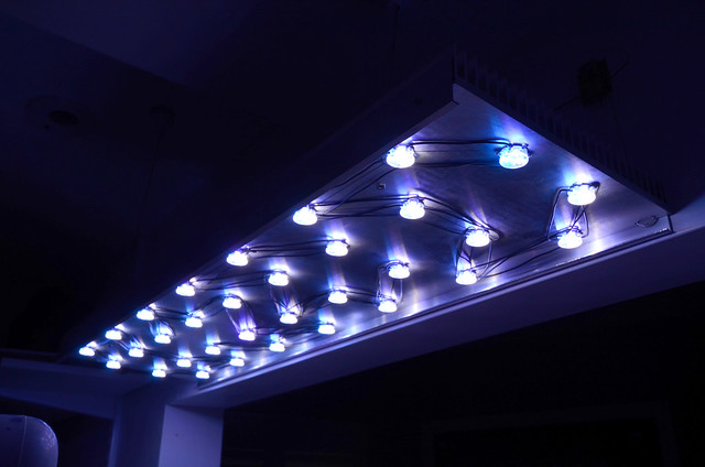 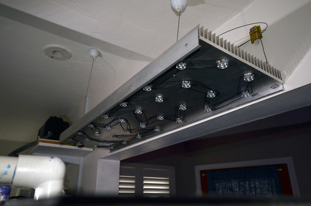 The controller is built into an old Pelican case I've had sitting around. It's a tad overbuilt hehe. 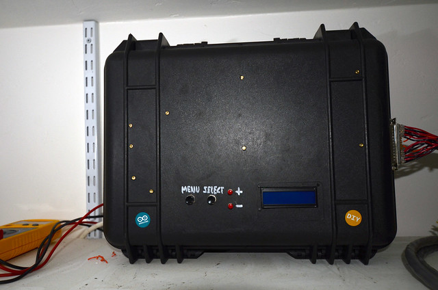 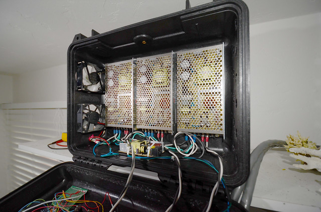 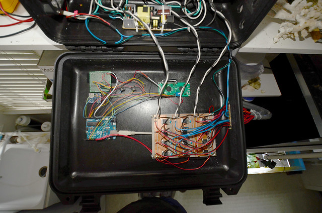 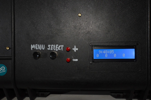
|
|
|
|
|
12/16/2011, 02:04 PM
|
#881 |
|
Registered Member
Join Date: Feb 2011
Posts: 70
|
Just noticed something...
The script is set up to use the EEPROM... but there's no "erase eeprom" function at the beginning of the script.. before writing to the eeprom. The eeprom's still holding values from the last time it was flashed/programmed. I'm playing with the original script.. not my modified version.. if I change values in the LED variables, it still loads whatever values were in the script the last time. I've verified this.. 3 times. Since we have the EEPROM library installed.. open the "eeprom_clear" example.. flash that before loading a newly revised script/sketch.. new values are now in control. Code:
/*
 * EEPROM Clear
 *
 * Sets all of the bytes of the EEPROM to 0.
 * This example code is in the public domain.

 */

#include "EEPROM.h"

void setup()
{
  // write a 0 to all 512 bytes of the EEPROM
  for (int i = 0; i < 512; i++)
    EEPROM.write(i, 0);

  // turn the LED on when we're done
  digitalWrite(13, HIGH);
}

void loop()
{
}
|
|
|
|
|
12/17/2011, 12:30 PM
|
#882 |
|
Registered Member
Join Date: Feb 2011
Posts: 70
|
Trying to hook in a relay function for the heatsink fans, but I can't figure out what to associate the lightsOff function to. I have a 5mm led connected to the relay pin for testing. I reconfigured the StartMins and PhotoPeriod for each channel to use a global StartMins and PhotoPeriod, so they all start and end the same time, but their individual fade functions are still functional. I then redid the menu to have a master "lights on" and "lights off" setting, followed by the individual fade and % settings for each channel. Figured having a master start and end function would be easier when hooking in a relay function.
If I use: Code:
if (Relay1 >= StartMins) {
   digitalWrite(Relay1, HIGH);
}
If I use: Code:
if (Relay1 <= StartMins) {
   digitalWrite(Relay1, HIGH);
}
Adding in: Code:
if (Relay1 <= StartMins) {
   digitalWrite(Relay1, HIGH);
  } else {
       if(Relay1 > (StartMins+PhotoPeriod)) {
   digitalWrite(Relay1, LOW);
         }
}
I managed a half-assed fix by putting it within the "led functions" section: Code:
/****** LED Functions ******/
/***************************/
//function to set LED brightness according to time of day
//function has three equal phases - ramp up, hold, and ramp down

int   setLed(int mins,         // current time in minutes
            int ledPin,        // pin for this channel of LEDs
            int start,         // start time for this channel of LEDs
            int period,        // photoperiod for this channel of LEDs
            int fade,          // fade duration for this channel of LEDs
            int ledMax,        // max value for this channel
            boolean inverted   // true if the channel is inverted
            )  {
  int val = 0;


      //// heatsink fan relay on /////////////////////////////////////////////
     if (mins > start || mins <= start + fade)  {
        digitalWrite(Relay1, HIGH);
      }
      //// heatsink fan relay off
      if (mins <= start || mins > start + period)  {
        digitalWrite(Relay1, LOW);
          }

      //////////////////////////////////////////////////////////////////////////

      //fade up
      if (mins > start || mins <= start + fade)  {
        val = map(mins - start, 0, fade, 0, ledMax);
      }
      //fade down
      if (mins > start + period - fade && mins <= start + period)  {
        val = map(mins - (start + period - fade), 0, fade, ledMax, 0);
      }
      //off or post-midnight run.
      if (mins <= start || mins > start + period)  {
        if((start+period)%1440 < start && (start + period)%1440 > mins )
          {
            val=map((start+period-mins)%1440,0,fade,0,ledMax);
          }
        else
        val = 0;
      }


    if (val > ledMax)  {val = ledMax;}
    if (val < 0) {val = 0; }

  if (inverted) {analogWrite(ledPin, map(val, 0, 100, 255, 0));}
  else {analogWrite(ledPin, map(val, 0, 100, 0, 255));}
  if(override){val=overpercent;}
  return val;
}
But now... when it shuts off, it still flickers.. very dimly. Is this normal? 
|
|
|
|
|
12/17/2011, 05:09 PM
|
#883 |
|
Registered Member
Join Date: Feb 2011
Posts: 70
|
Think it's a ghost in my script. Playing with the original Typhon script, and the led keeps flickering. Modify the script I posted here with the 6 PWM channels.. and the led doesn't flicker. In fact.. it's about 1/2 as bright for some reason. Still hooking the relay controls in with the led functions, as I haven't tried hooking it in separately yet. It's working.. I don't want to screw it up now
 . .But it is strange that earlier it was twice as bright when "high", and flickering when "low". Definitely had something in the script screwing it up. Now to play with some heat sensors..... |
|
|
|
|
12/17/2011, 06:10 PM
|
#884 | |
|
Registered Member
Join Date: Sep 2011
Posts: 22
|
Quote:
Thanks |
|
|
|
|
|
12/17/2011, 07:02 PM
|
#885 | |
|
Registered Member
Join Date: Sep 2004
Posts: 55
|
Quote:
I did wire them so that each color is dimmed independently. That way the overall color is easily tuned, and I'm a big fan of the pure "actinic" look for sunrise and sunset ... and showing off! 
|
|
|
|
|
|
12/18/2011, 10:11 AM
|
#886 |
|
Registered Member
Join Date: Feb 2011
Posts: 70
|
Cutter Electronics in Australia are selling 3-up Cree's. They even have 7-up designs.
|
|
|
|
|
12/18/2011, 12:28 PM
|
#887 |
|
Registered Member
Join Date: Feb 2011
Posts: 70
|
I just noticed that Megablue used the adc keys in his design. I just can't get the sketch to compile.. "two wire" errors.
http://www.reefcentral.com/forums/sh...&postcount=757 |
|
|
|
|
12/22/2011, 10:02 AM
|
#888 |
|
Registered Member
Join Date: Feb 2011
Posts: 70
|
Just found the actual libraries for using an external eeprom chip
.AT24C1024 I2C EEPROM Library: http://arduino.cc/playground/Code/I2CEEPROM24C1024 The 24C256 library: http://www.arduino.cc/playground/Code/I2CEEPROM The 24C512 library: http://www.arduino.cc/playground/Code/I2CEEPROM24LC512 Download: http://code.google.com/p/arduino-at2...downloads/list Implementing this into the Typhon would definitely speed things up .
|
|
|
|
|
12/26/2011, 10:47 AM
|
#889 |
|
Registered Member
Join Date: Jan 2003
Location: NB, Canada
Posts: 215
|
Looking for 2 of the typhoon rev 1.0 boards, and any leftovers for the build. Please pm me if you have a couple of spares.
|
|
|
|
|
12/26/2011, 04:47 PM
|
#890 | |
|
Registered Member
Join Date: Aug 2009
Location: France
Posts: 14
|
Quote:
|
|
|
|
|
|
12/28/2011, 02:27 PM
|
#891 |
|
Registered Member
Join Date: Feb 2011
Posts: 70
|
Found a script with a good example of using the adc_keys... not the Typhon, but good info for modifying Typhon to use the single wire key pad.
|
|
|
|
|
12/29/2011, 08:02 AM
|
#892 | |
|
Registered Member
Join Date: Jul 2011
Posts: 118
|
Quote:
That's way over my head! I did look the project up after looking at the code and found the whole thing in a great PDF file. There is some very interesting and adaptable parts here. I love the Nokia 3310 screen with joystick. http://code.google.com/p/dangerduino...erManualv1.pdf shark boy |
|
|
|
|
|
01/02/2012, 10:10 AM
|
#893 |
|
Registered Member
Join Date: Jan 2003
Location: NB, Canada
Posts: 215
|
Still looking...
If anyone has a spare PCB, shoot me a pm. Thanks |
|
|
|
|
01/03/2012, 04:05 PM
|
#894 |
|
Registered Member
Join Date: Jul 2011
Posts: 118
|
|
|
|
|
|
01/10/2012, 08:07 PM
|
#895 |
|
Registered Member
Join Date: Jan 2003
Location: NB, Canada
Posts: 215
|
Dwizum (or anyone with hardware design knowledge
.)
What would your thoughts be about adding a bridge rectifier like a DF02M to this design? It could provide reverse polarity protection for the circuit, and even accept AC adapters for that matter. Cost would be very minimal, and give you the ability to use a wide range of wall warts. Is there a downside to using one, other than the voltage drop across the rectifier? Would the DF02M, and a 100uf cap be good for this application? Also, I noticed when trying to create the gerbers for ITead, if you use THEIR cam to generate the gerbers, it messes up the drill file for some reason. You can see it if you use a gerber viewer. I used the cam from Seeed, and copied the drill file over with the rest of the files for ITead, everything "looks" proper now. Chris |
|
|
|
|
01/16/2012, 06:52 PM
|
#896 | |
|
Registered Member
Join Date: Feb 2011
Posts: 70
|
Quote:
DF02M, DF04M.. both will work fine. As long as the Arduino doesn't need more than 1.5A that is...
|
|
|
|
|
|
01/16/2012, 07:04 PM
|
#897 |
|
Registered Member
Join Date: Feb 2011
Posts: 70
|
Adafruit delivery finally came.. new bigger LCD and some Dallas Temperature sensors
 . .   Code:
#define ONE_WIRE_BUS 2                  //data wire for temperature probes.
#define TEMPERATURE_PRECISION 9
OneWire oneWire(ONE_WIRE_BUS);
DallasTemperature sensors(&oneWire);
DeviceAddress TempSense_1, TempSense_2, TempSense_3;

-
-
-
-
-

//////////////   TEMPERATURE   //////////////

void printAddress(DeviceAddress deviceAddress)
{
	for (uint8_t i = 0; i < 8; i++)
	{
		// zero pad the address if necessary
		if (deviceAddress[i] < 16) Serial.print("0");
		Serial.print(deviceAddress[i], HEX);
	}
}
void printTemperature(DeviceAddress deviceAddress)
{
	float tempC = sensors.getTempC(deviceAddress);
	lcd.print(DallasTemperature::toFahrenheit(tempC), 1);
}
void printData(DeviceAddress deviceAddress)
{
	Serial.print(" ");
	printTemperature(deviceAddress);
	Serial.println();
}

-
-
-
-
-

//////////////    Get temp data from DS18B20   //////////////

	Serial.begin(9600);
	sensors.begin();
	if (!sensors.getAddress(TempSense_1, 0));
	if (!sensors.getAddress(TempSense_2, 1));
	if (!sensors.getAddress(TempSense_3, 2));
	sensors.setResolution(TempSense_1, 9);
	sensors.setResolution(TempSense_2, 9);
	sensors.setResolution(TempSense_3, 9);

-
-
-
-
-

//////////////    Display HeatSink Temperature   //////////////

		sensors.requestTemperatures();

		lcd.setCursor(0,2);
		lcd.print("Temp1");
		lcd.setCursor(0,3);
		printData(TempSense_1);
		lcd.print((char)223); //print degree symbol °
		lcd.print("F ");
		lcd.setCursor(7,2);
		lcd.print("Temp2");
		lcd.setCursor(7,3);
		printData(TempSense_2);
		lcd.print((char)223); // print degree symbol °
		lcd.print("F ");
		lcd.setCursor(14,2);
		lcd.print("Temp3");
		lcd.setCursor(14,3);
		printData(TempSense_3);
		lcd.print((char)223); // print degree symbol °
		lcd.print("F");
               if((StartMins < minCounter && StopMins >= minCounter)) {
                  lcd.setCursor(16,0);
                  lcd.print("ON ");
                  }

	          else{
                  lcd.setCursor(16,0);
                  lcd.print("OFF");

                  }
}
My fixture is going to be 3 sections, 3 heatsinks. So I want 3 temp sensors. Although all 3 sensors are working, I noticed something strange. In my picture above.. the sensor to the left is reading as #1, the middle sensor is reading as #3, and the sensor to the right is reading as #2. ??? What did I do wrong? |
|
|
|
|
01/16/2012, 09:02 PM
|
#898 | |
|
Registered Member
Join Date: Jun 2009
Location: Wethersfield, CT
Posts: 375
|
Quote:
|
|
|
|
|
|
01/16/2012, 09:05 PM
|
#899 | |
|
Registered Member
Join Date: Jun 2009
Location: Wethersfield, CT
Posts: 375
|
Quote:
|
|
|
|
|
|
01/16/2012, 09:54 PM
|
#900 |
|
Registered Member
Join Date: Feb 2011
Posts: 70
|
Fixed it.
Just swapped the 2 sensors themselves.. now they read in succession. Guess it was the internal addresses. |
|
|
|
|
|
|
 Similar Threads
|
||||
| Thread | Thread Starter | Forum | Replies | Last Post |
| Cheap Moonlight | ticklesworth | New to the Hobby | 3 | 04/04/2010 04:09 PM |
| Cheap Moonlight | ticklesworth | Do It Yourself |
0 | 04/03/2010 08:52 AM |
| Arduino base controller - power pack ONLY TODAY | MaLi | Do It Yourself |
0 | 03/07/2010 05:56 AM |
| Sumps 101: Cheap, simple and effective for small tanks | cody6766 | Central Oklahoma Marine Aquarium Society | 8 | 01/06/2009 10:57 AM |


