
|
|
|
|||||||
 |
| Thread Tools |
 09/22/2010, 03:35 PM
|
#151 |
|
Premium Member
 Join Date: Feb 2001
Location: Park Ridge
Posts: 2,232
|
DWZM
Thanks Bill
__________________
NKAWTG Current Tank Info: 570 Soft/LPS, 330SPS & 440 refug |

|

|
|
09/30/2010, 09:57 PM
|
#152 |
|
Premium Member
Join Date: Feb 2001
Location: Park Ridge
Posts: 2,232
|
DWZM
Any Updates....??? Currently Not easy to swallow??? There are lots of us who still change our own oil and can solder but are are not a Double E. I'm thinking on just dropping the bomb and purchasing an Apex controller simply to control my LED lights. Results matter...Any thing new...5/12 or five+ months later...Whats up? Anything that most of us can work with?...Impove on...? Or Should I just go with an Apex Controller? Bill
__________________
NKAWTG Current Tank Info: 570 Soft/LPS, 330SPS & 440 refug Last edited by wld1783; 09/30/2010 at 10:06 PM. |
|
|
|
|
09/30/2010, 10:22 PM
|
#153 |
|
Registered Member
Join Date: Apr 2010
Location: Texas
Posts: 1,532
|
If you check the other thread: http://www.reefcentral.com/forums/sh....php?t=1783536
There has been a lot of progress. One person even has the LED control coded in. We have almost solved the last problem with the design so it shouldn't be long now for an "initial" release version. You don't have to be an EE to do this stuff(though I'm heading that route). The whole idea behind these designs are that in the end, anyone with decent soldering skills and the ability to analyze examples will be able to create their own custom controller SEVERAL hundred dollars cheaper with even more functionality. As for which to go with, that's entirely up to you. A commercial controller will get you up and running almost immediately, but building yours will take a bit of time. Just have to ask yourself if you feel like doing a neat project or if your time/interest is worth $500 more. |
|
|
|
|
10/01/2010, 04:39 AM
|
#154 |
|
Team RC Member
Join Date: Sep 2003
Location: NY
Posts: 17,749
|
Dustin, to be fair, this thread reflects the Typhon project, a different project than the Hydra, though of course they're fairly related (both being open source Arduino projects for reef tanks).
Bill, I'm sorry, I haven't had time to work on this project much in the last week.
__________________
Inconveniencing marine life since 1992 "It is my personal belief that reef aquaria should be thriving communities of biodiversity, representative of their wild counterparts, and not merely collections of pretty specimens growing on tidy clean rock shelves covered in purple coralline algae." (Eric Borneman) |
|
|
|
|
10/01/2010, 06:31 AM
|
#155 | |
|
Registered Member
Join Date: Jun 2007
Location: Waterford, MI
Posts: 790
|
Quote:

|
|
|
|
|
|
10/01/2010, 06:41 AM
|
#156 |
|
Team RC Member
Join Date: Sep 2003
Location: NY
Posts: 17,749
|
Actually the real trick is I have an evil twin that I keep locked up working on reef projects all day.

__________________
Inconveniencing marine life since 1992 "It is my personal belief that reef aquaria should be thriving communities of biodiversity, representative of their wild counterparts, and not merely collections of pretty specimens growing on tidy clean rock shelves covered in purple coralline algae." (Eric Borneman) |
|
|
|
|
10/01/2010, 07:09 AM
|
#157 | |
|
Registered Member
Join Date: Apr 2010
Location: Texas
Posts: 1,532
|
Quote:
No kidding, you do seem to cram a lot into the day. After work I can hardly bring myself to feed the fish. |
|
|
|
|
|
10/01/2010, 07:20 AM
|
#158 |
|
Team RC Member
Join Date: Sep 2003
Location: NY
Posts: 17,749
|
Fair enough! This Typhon project is definitely on a smaller scale than the Apex or any other full-functioning commercial controller, and such controllers are definitely more in the realm of the Hydra.
Though, on that note, I did put pinouts for I2C and TTL serial on the Typhon, so if someone started with a Typhon and later decided they wanted to do MORE than just control LEDs, it would be really easy to add "expansion modules" to include other functionality - control of a relay board, or reading temperature and pH, and so on. Once I get the basic Typhon out the door, I'm hoping to work on some "reference designs" for such expansion modules.
__________________
Inconveniencing marine life since 1992 "It is my personal belief that reef aquaria should be thriving communities of biodiversity, representative of their wild counterparts, and not merely collections of pretty specimens growing on tidy clean rock shelves covered in purple coralline algae." (Eric Borneman) |
|
|
|
|
10/01/2010, 07:26 AM
|
#159 |
|
Registered Member
Join Date: Apr 2010
Location: Texas
Posts: 1,532
|
That is an awesome idea. I am really starting to love the scalability/ease of the Arduino based AVR.
|
|
|
|
|
10/01/2010, 07:42 AM
|
#160 |
|
Team RC Member
Join Date: Sep 2003
Location: NY
Posts: 17,749
|
It would even be easy to get two Typhons to talk to each other - I know there are at least a few people with prototype boards who plan on having multiples. Or, get a Typhon talking to a Hydra. I will probably do that on my 360g. In fact I hope to put a Typhon on it within the next week to start playing with test LED rigs before I design my final build.
__________________
Inconveniencing marine life since 1992 "It is my personal belief that reef aquaria should be thriving communities of biodiversity, representative of their wild counterparts, and not merely collections of pretty specimens growing on tidy clean rock shelves covered in purple coralline algae." (Eric Borneman) |
|
|
|
|
10/02/2010, 04:35 PM
|
#161 |
|
Registered Member

Join Date: Dec 2005
Location: Scotts Valley, Ca.
Posts: 661
|
Love this thread, just one more thing to DIY.
Would the Arduino Uno work? I think it has the same chip mentioned earlier and it already has the USB built in (I think). Is there a material list, or did I miss it? Ie... X board will work with Y LCD and you need ....etc. Oh yea, DWZM you are the man!! Thanks for all of the hard work. Aaron
__________________
Each day infuses us with the knowledge we carry into tomorrow. Current Tank Info: Anemones, Zoas and Shrooms |
|
|
|
|
10/02/2010, 06:06 PM
|
#162 |
|
Team RC Member
Join Date: Sep 2003
Location: NY
Posts: 17,749
|
The Uno is simply the latest reference design for the official Arduino hardware platform. It would certainly work as an LED controller, as just about any other official Arduino hardware (and many clones) would. The difference is, this device (the Typhon) has a few "extra" components built right in to the board, such that you don't have to add them on your own via breakout boards or shields. This makes the Typhon essentially a single-task design, in that it's designed for controlling LEDs. Meanwhile the Uno is a general purpose prototyping platform, meaning it doesn't really do ANYTHING on it's own, but you can add to it/build on it to do a wide range of things.
There are advantages and disadvantages to either approach, of course. For one thing, unless you really find some great deals, the all-in-one approach of the Typhon will probably be cheaper than buying an Uno, RTC breakout, PWM level shifting breakout, breakout or shield for the buttons, connector for the LCD, etc. Also, having everything on a single PCB is probably perceived by many people to be a "simpler" or "cleaner" approach, as you don't need a mess of jumpers, cables, and so on wiring everything together, and you don't even have to understand how the different components need to be connected, since it's all built in to the board.
__________________
Inconveniencing marine life since 1992 "It is my personal belief that reef aquaria should be thriving communities of biodiversity, representative of their wild counterparts, and not merely collections of pretty specimens growing on tidy clean rock shelves covered in purple coralline algae." (Eric Borneman) |
|
|
|
|
10/02/2010, 07:43 PM
|
#163 |
|
Registered Member
Join Date: Dec 2005
Location: Scotts Valley, Ca.
Posts: 661
|
I was thinking for it less complicated to just buy a premade board, but I may be wrong.
I am only looking to control 2 drivers for DIY Cree lights, so maybe I do not need all of the extra functions of the uno? Or does the uno not have any functions on it's own? Now I am confused. I think if I had a parts list and a wiring diagram I could wire it up, but I do not have the knowledge to put it together on my own. Man am I envious of those who can. Thanks, Aaron
__________________
Each day infuses us with the knowledge we carry into tomorrow. Current Tank Info: Anemones, Zoas and Shrooms |
|
|
|
|
10/03/2010, 05:38 AM
|
#164 | ||
|
Team RC Member
Join Date: Sep 2003
Location: NY
Posts: 17,749
|
Quote:
 Quote:
For instance, if the drivers you are planning on using operate at 10v (i.e. the Meanwell ELNs) then the Uno plain won't work on it's own - it operates at 5v, so you need level shifting circuits between the Uno and the drivers. On the other hand, if you have Buckpucks or other 5v-logic drivers, you can probably use the Uno to dim them without any external circuitry. That said, you'll also probably need hardware/software to let you interface with the Uno (i.e. buttons and a screen) and/or to otherwise facilitate dimming. For instance, the Uno on it's own has no concept of time, other than counting milliseconds in a rather inaccurate manner - if you want to do time-based things, like fade the lights on and off at certain times, you really need to get an RTC (real time clock) as well. So, really, it comes down to your philosophical approach - would you rather buy a generic off the shelf controller (the Uno) and a few off the shelf breakout boards, then wire them together on your own, and upload the software? Or, would you rather solder together a single board that has everything it needs onboard? On the one hand, you're wiring together a bunch of off the shelf boards. On the other hand, you're assembling a single "custom" board. Some will like one path, others will like the other path.
__________________
Inconveniencing marine life since 1992 "It is my personal belief that reef aquaria should be thriving communities of biodiversity, representative of their wild counterparts, and not merely collections of pretty specimens growing on tidy clean rock shelves covered in purple coralline algae." (Eric Borneman) |
||
|
|
|
|
10/03/2010, 09:16 AM
|
#165 |
|
Registered Member
Join Date: Dec 2005
Location: Scotts Valley, Ca.
Posts: 661
|
Since you put it that way, I would rather have one custom board, which is what this thread is all about.
I guess I will just wait until you release all the schematics. And since I do not even have LED's yet... boy am I impatient! Sorry for all the questions, I feel like some of them a "stupid questions" so thank you in advance. Aaron
__________________
Each day infuses us with the knowledge we carry into tomorrow. Current Tank Info: Anemones, Zoas and Shrooms |
|
|
|
|
10/04/2010, 08:00 AM
|
#166 | ||
|
Team RC Member
Join Date: Sep 2003
Location: NY
Posts: 17,749
|
Quote:
Quote:
__________________
Inconveniencing marine life since 1992 "It is my personal belief that reef aquaria should be thriving communities of biodiversity, representative of their wild counterparts, and not merely collections of pretty specimens growing on tidy clean rock shelves covered in purple coralline algae." (Eric Borneman) |
||
|
|
|
|
10/04/2010, 09:19 AM
|
#167 |
|
Registered Member
Join Date: Dec 2005
Location: Scotts Valley, Ca.
Posts: 661
|
After looking again, I found the link and downloaded Eagle so I can view the info. I will be getting my LED's soon and then I will attempt this controller.
Thanks again, Aaron
__________________
Each day infuses us with the knowledge we carry into tomorrow. Current Tank Info: Anemones, Zoas and Shrooms |
|
|
|
|
10/11/2010, 06:49 AM
|
#168 |
|
Team RC Member
Join Date: Sep 2003
Location: NY
Posts: 17,749
|
Since there are at least a few people with these in-hand or in-construction, I wanted to add a few quick notes about actual use.
First, a photo. Excuse the fact that there are missing components and other "issues" as this was an early prototype I was messing around with. It's also important to note that this is from the first run of boards - the files uploaded have some silkscreen text fixes I'll point out below. 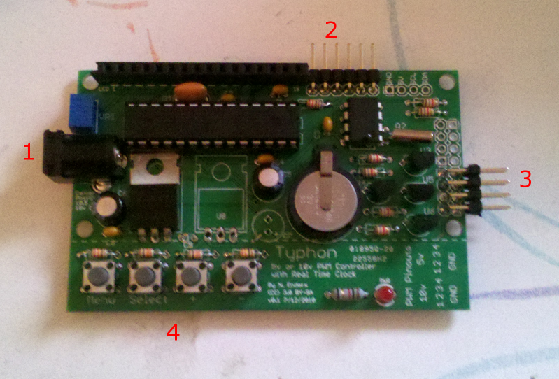 This is the Typhon without the LCD plugged in, so you can see the guts. There are 4 areas of interest with red numbers: 1) The DC power jack. You need a 12 - 18v (plus or minus) wall wart with a 2.1mm center positive plug. This is a very common plug so it should be easy to find. 2) The FTDI programming header. This is a header you'd plug an external TTL serial-USB converter in to, i.e. an FTDI cable or breakout board, to upload new firmware. If you don't intend on changing the firmware code, you can ignore this once the unit has been initially programmed. If you are plugging something in here to program, make sure you check polarity - for some common FTDI breakouts, the header is "upside down" - for example, to use my USB-BUB, I plug it in with the components on the USB-BUB facing down. No biggie, just make sure yours is plugged in correctly before use by looking at the order of the pinout. 3) The output header. This is a 2-row 90 degree header for connecting your LED drivers. There are actually two 4-pair headers right next to each other, depending on if you're using 5v or 10v outputs. The bottom 4, populated in this photo, are for 10v PWM outputs (i.e. meanwell ELN drivers). The top four, not populated, are for 5v outputs (i.e. buckpucks or most DIY drivers). You only need to populate the four you'll actually be using, no sense wasting headers if you'll never need them. It's VERY IMPORTANT to get polarity correct here, and this is where the silkscreen was corrected. In this 1st-run prototype board, the silk labels - down below the pins on the empty section of board - are BACKWARDS. If you look at the header from the side of the board, the ground pins are the TOP of each pair, and the signal (positive) pins are the BOTTOM of each pair. These are standard .1" male headers I used on this board, so you can use any common square pin .1" female connector - so called "header connectors" or even bits of female headers, or whatever your preference is. These are very common at hobby electronics vendors, and at hobby shops that deal in R/C hobbies, since R/C receivers use .1" connectors, too. As mentioned elsewhere, the intent of this device is to control 4 channels of lighting - so there are 4 pairs of connections in these headers, numbered 1-4, from bottom to top. Each of these is a "channel" and can control many drivers - so if you had 8 meanwells, you could put two on each channel, or one each on the first three channels and then 5 on the 4th channel - and so on. Each channel can handle a few hundred mA of current, which should be more than any of us ever needs. 4) The buttons. Will be explained below. There are some other areas of interest not labeled here. First, the long header in the upper left is a 16-pin header to connect an LCD - the board is designed for a 16x2 LCD which is pretty common, and is what's shown in the photos earlier in this thread. The little blue box between that header and the DC power jack is a trimpot to adjust contrast on the LCD. Brightness on the LCD is controlled by a PWM pin that the firmware manages. To the right of the FTDI header is a 4 pin header not populated in this photo. This is an I2C header, intended for eventual expansion - i.e. if someone wanted to use this controller to monitor temperature or pH, all you'd have to do is design an I2C-based sensor and plug it in there. Or you could do a relay board to have the unit turn things on and off. The possibilities are pretty endless as there are lots of I2C devices out there. It's not populated in this photo because unless someone is going to go develop an expansion module, there's really no use for this header at this time. In the middle of the board is the backup battery for the real time clock. This allows the device to retain time and date when it's unplugged. This battery should, in theory, last for years of unplugged use, and infinitely if the device is plugged in, so you should never need to change it. And FWIW, the firmware stores configuration variables (settings for the LEDs) in EEPROM, so it retains your configuration when the power goes out - no "blinking 12:00" with this device! There are 4 holes in the board to allow for mounting. They line up with holes in the corners of most 16x2 LCDs. The holes in the board will allow for M3 or M2.5 threaded fasteners (bolts, standoffs, etc). Most LCDs have M2.5 holes. So, you could put standoffs between the Typhon board and the LCD, or use long through-bolts with spacers to mount the whole thing to a panel under your tank, or in a project box, or whatever else you wanted to do. On to use. Keep in mind that this description is for the default firmware I've developed - people can write their own firmware to behave however they want. When the device is powered up, it displays a welcome message, then defaults to a main screen that shows the time and the percentage that each of the 4 channels is currently running at. This gives you a quick status of the unit. After a set amount of time, the backlight on the LCD drops down to a dim setting so that the light given off by the unit won't be obtrusive. When you use the buttons to operate the unit, the backlight jumps back up so you can see what you're doing. There are four buttons: menu, select, plus, and minus. Menu is used to cycle through the setting menus for the device. Select is currently not used, it's basically there to allow for future expansion. Plus and minus adjust the setting for whichever screen you're on. So, to configure the device, you push menu to cycle through the various menus, and plus or minus to adjust the settings displayed. For each of the 4 channels, there are 4 settings: 1) Start time - time the lights turn on. 2) End time - time the lights turn off. 3) Fade duration - minutes/hours it takes for the LEDs to fade from zero to full power and vice-versa. 4) Max intensity - percentage of max power that the drivers hit when full-on. So, basically, at the start time, the LEDs turn on and begin to fade up towards the max intensity percentage, which they reach after the fade duration has elapsed. Then, in the evening, the reverse process happens. Besides those screens to set up the LED channels, there are screens to adjust the hours and minutes for the time setting on the unit. That should be about it!
__________________
Inconveniencing marine life since 1992 "It is my personal belief that reef aquaria should be thriving communities of biodiversity, representative of their wild counterparts, and not merely collections of pretty specimens growing on tidy clean rock shelves covered in purple coralline algae." (Eric Borneman) |
|
|
|
|
10/11/2010, 07:25 AM
|
#169 |
|
Registered Member
Join Date: Jul 2007
Location: Puerto Rico
Posts: 673
|
Thanks a lot for the write up DWZM! As soon as I get mine it should be pretty easy to set it up. Instructions are clear and looks like the firmware is very easy to follow and adjust. Can't wait to get my hands on it.
|
|
|
|
|
10/11/2010, 07:39 AM
|
#170 |
|
Registered Member
Join Date: Mar 2008
Location: bronx
Posts: 52
|
hey dwzm the board i got from you is awesome. im still a little confused as to where i hook up my drivers. i know the drivers get hooked up to the double pi on the right side of the board. now where i am gettting confussed is i have meanwell drivers and you were saying something about 5v connection and 10v connection. i need to hook it up 10v connection. how to i go about this. what is the posative and what is the negatime. do you think you can post a pic with the side view of the board explaining this. thanks. and you really are a great reefer.
|
|
|
|
|
10/11/2010, 08:03 AM
|
#171 | |
|
Registered Member
Join Date: Jun 2007
Location: Waterford, MI
Posts: 790
|
Quote:
As explained above, the positive is the bottom, our outside-most pin, the negative is the top, or inside. cant wait to get my hands on mine! |
|
|
|
|
|
10/11/2010, 09:19 AM
|
#172 |
|
Premier World Traveler
Join Date: Nov 2000
Location: Ohio
Posts: 4,293
|
Not what I was expecting. The through hole mounting makes things much easier. I had SMT in my head for some reason. Looks like a sweet setup. My fish will love you in the morning DWZM!
__________________
"The moment you doubt whether you can fly, you cease forever to be able to do it..." J.M. Barrie Current Tank Info: 210 AGA RR, Apex, 3x Kessil A360W & 2x 80W T5s, GEO 618 Ca Rx, BM220 CS2 skimmer, Tunze 6100s, 42" ETSS/AE Tech refugium/sump |
|
|
|
|
10/11/2010, 09:41 AM
|
#173 |
|
Team RC Member
Join Date: Sep 2003
Location: NY
Posts: 17,749
|
I would actually like to do an SMT version of this or the Hydra. Once you are used to it, SMT is convenient and fast as long as none of the parts are tiny. With through hole you spend a lot of time flipping the board over, bending leads, trimming leads, so on. The real holdup for an all-SMT Arduino-based project is that you have to burn the bootloader in circuit, which means you can't buy a bootloaced chip. Plus the only SMT packages the AVRs come in are a little daunting. So I figured an SMT design would alienate a large percentage of the folks who might want to try building one of these.
__________________
Inconveniencing marine life since 1992 "It is my personal belief that reef aquaria should be thriving communities of biodiversity, representative of their wild counterparts, and not merely collections of pretty specimens growing on tidy clean rock shelves covered in purple coralline algae." (Eric Borneman) |
|
|
|
|
10/13/2010, 02:46 PM
|
#174 |
|
Registered Member
Join Date: Jul 2007
Location: Puerto Rico
Posts: 673
|
Just got my Typhon working and its amazing! I love how easy is to change settings with the on board buttons. Also gotta love the nice Blue/ white LCD screen.
Have anyone done a housing box for the electronics? I'd like to make one but need to figure out what to do with the buttons |
|
|
|
|
10/13/2010, 03:27 PM
|
#175 |
|
Registered Member
Join Date: Apr 2010
Location: Texas
Posts: 1,532
|
You can get some caps similar to this:
http://www.rapidonline.com/productin...moduleno=80568 Don't know which ones right off hand. I know they make all different styles and colors. |
|
|
|
|
| Thread Tools | |
|
|
 Similar Threads
|
||||
| Thread | Thread Starter | Forum | Replies | Last Post |
| Cheap Moonlight | ticklesworth | New to the Hobby | 3 | 04/04/2010 04:09 PM |
| Cheap Moonlight | ticklesworth | Do It Yourself |
0 | 04/03/2010 08:52 AM |
| Arduino base controller - power pack ONLY TODAY | MaLi | Do It Yourself |
0 | 03/07/2010 05:56 AM |
| Sumps 101: Cheap, simple and effective for small tanks | cody6766 | Central Oklahoma Marine Aquarium Society | 8 | 01/06/2009 10:57 AM |


