
|
|
 06/08/2018, 12:15 PM
|
#26 | |
|
Registered Member
Join Date: Jul 2016
Location: Richmond, Texas
Posts: 111
|
Quote:
|
|

|

|
|
06/08/2018, 12:16 PM
|
#27 | |
|
Registered Member
Join Date: Sep 2003
Location: North Carolina
Posts: 20,050
|
Quote:
For 6 LDDs you would simply need to run 6 wires (6 black and 6 red) from the + and - VDC outputs on the meanwell power supply instead of the one set he shows there..
__________________
Who me? |
|
|
|
|
|
06/08/2018, 12:21 PM
|
#28 | |
|
Got Reef
 Join Date: Mar 2006
Location: Weeki Wachee, Florida
Posts: 2,501
|
Quote:
Each board has an INPUT and OUTPUT cat5? network receptacle. My setup uses 6 boards. The BlueFish is on the 1st board. A network cable goes from the OUTPUT on board #1 to the INPUT on board #2, and so on. The cables carry the PWM data from the BlueFish to each board, on after another.
__________________
Tom No matter how much you try to push the envelope, it remains stationary. |
|
|
|
|
|
06/08/2018, 12:28 PM
|
#29 | |
|
Registered Member
Join Date: Sep 2003
Location: North Carolina
Posts: 20,050
|
Quote:
 Correct me if I'm wrong but you have.. 1 bluefish mini.. 6 of the o2 boards which have 6 LDDs on each right for a total of 36 LDD modules? So you have 6 different lighting channels with 6 LDDs on each channel? AFAIK the in/output cat 5 are just jumper wires allowing one bluefish to control multiple boards by simply jumpering the PWM from the one board to others.. (again.. I have not used nor done any studying of o2's stuff beyond a 4 second glance)
__________________
Who me? |
|
|
|
|
|
06/08/2018, 12:34 PM
|
#30 | |
|
Got Reef
Join Date: Mar 2006
Location: Weeki Wachee, Florida
Posts: 2,501
|
Quote:
----------------------------------------- It's terrible having to hear about Aaron. I didn't really know him that well but, whenever I talked to him, he was always very helpful. Simply a nice and friendly human being. I've had colon and liver cancer for 7 years. Seems like someone is on my side as I'm doing relatively well. My wife and I will be praying for him and his family.
__________________
Tom No matter how much you try to push the envelope, it remains stationary. |
|
|
|
|
|
06/08/2018, 12:41 PM
|
#31 | |
|
Registered Member
Join Date: Feb 2009
Location: Greensboro, NC
Posts: 766
|
Quote:
__________________
Dave Current Tank Info: 35g Shallow Reef Build/iTech 100/Tunze Osmolator/MP20/Sunpower |
|
|
|
|
|
06/08/2018, 01:37 PM
|
#32 | |
|
Got Reef
Join Date: Mar 2006
Location: Weeki Wachee, Florida
Posts: 2,501
|
Quote:
The question confuses me. Maybe describing my setup will help: The pic shows Top and Bottom of a single heat sink:  1. Six 2ft long heatsinks 2. Twelve Lumia 5.2 70W (5 channel) LED chips - 2 on each heat sink connected together in series. Then 5+ wires and 5- wires to the PCB (for the 5 channels) 3. Six O2Surplus 6 channel LDD boards - 1 on each heat sink, each holds 5 LDDs. The ONLY connection between these 6 boards is the cat5 (MWM) cable. 4. Three MW NES 350W 48V power supplies - Each of these powers 4 LED chips (280W) / the contents of 2 heat sinks 5. A BlueFish Mini controller - the controller is on the first (of 6) PCBs
__________________
Tom No matter how much you try to push the envelope, it remains stationary. |
|
|
|
|
|
06/08/2018, 05:04 PM
|
#33 | ||
|
Registered Member
Join Date: Apr 2013
Posts: 1,793
|
Yea AFAICT the Cat 5 only carries the 5v PWM signal. Believe the board has a 5V "boost" so as to not lose current down the line.
Depending on how far each is you may or may not be able to just parallel the LDD's Then again, maybe not ... Quote:
Err.. getting confusing the more I read about the jumpers.. AHHH.. now I found it... Quote:
Last edited by oreo57; 06/08/2018 at 05:48 PM. |
||
|
|
|
|
06/08/2018, 06:51 PM
|
#34 |
|
Got Reef
Join Date: Mar 2006
Location: Weeki Wachee, Florida
Posts: 2,501
|
oreo - now I understand - I think. If there just wasn't a grey mist covering everything.
 So, all I have to do is start with 6 normal 5up LDD boards, add 6 Zeners, 5V and 2 cat5 sockets. Then attach the BlueFish to the first board and connect the boards together with cat5. Actually, I read somewhere the 7th and 8th conductors were 5V and ground. Somehow the ground was very important. Am I getting it at all?
__________________
Tom No matter how much you try to push the envelope, it remains stationary. |
|
|
|
|
06/08/2018, 08:12 PM
|
#35 | |
|
Registered Member
Join Date: Apr 2013
Posts: 1,793
|
Quote:
|
|
|
|
|
|
06/09/2018, 01:09 PM
|
#36 |
|
Got Reef
Join Date: Mar 2006
Location: Weeki Wachee, Florida
Posts: 2,501
|
So, I'm gonna try and repair these boards...
 This is an Eagle(?) image of the board:  I've stared and stared at the pic and think I see a way to repair the damage. I would like to ask you experts a couple of questions before I start. Q1 - You'll notice that where each LDD fits on the board, there is a 10K SMD resister. The resister R2 where LDD-1 is was turned to dust. First, can I replace it with a normal 1/4W resister? Q2 - Notice the thin red trace which goes through the resister; the trace looks like it only goes to one terminal of the SMD and then continues to the PWM pin on the LDD. If that is so, then the other end of the resister must be soldered to the base of the PCB? If I measure resistance from the LDD PWM pin to the cat5 output pin (where the trace goes) I get 9940 Ohms. I get the same value if I measure from the LDD PWM pin to the base of the PCB. If the traces go to one end of the SMD and continue from the other end, wouldn't the images of the traces be illustrated differently? ----------------------------------------------------------------------------- I think I made a total mess of describing what I'm talking about... If it helps, here is a damaged board:  Any help would be helpful.
__________________
Tom No matter how much you try to push the envelope, it remains stationary. |
|
|
|
|
06/09/2018, 04:13 PM
|
#37 | |
|
RC Sponsor
Join Date: Sep 2009
Posts: 14,173
|
Quote:
__________________
Director Customer Support Royal Exclusiv USA For All Royal Exclusiv & Bubble King questions please refer to our Sponsor forum: http://www.reefcentral.com/forums/fo...play.php?f=745 Current Tank Info: 480G display mixed reef, 90G sump, 90G refugium, 60G display refugium. Check out my build thread: http://www.reefcentral.com/forums/showthread.php?t=1783476 |
|
|
|
|
|
06/09/2018, 06:02 PM
|
#38 |
|
Registered Member
Join Date: Apr 2013
Posts: 1,793
|
First I'll agrre w/ the above..
Then r2-7 are pull down resistors to turn the LDD's off in the event of controller failure (W/ out it the LDD's will just go to full).. Technically they ar unnecessary, and in this case it will complicate things because until you get all control circuits working your LED will never light.. complicates troubleshooting. HEF405ob is a non inverting buffer (sounds like I know something) so I assume that's what O2surplus used to "buffer" the PWM line output to the other boards.. https://assets.nexperia.com/document...t/HEF4050B.pdf Bottom right fried chip looks to be this: http://www.ti.com/lit/ds/symlink/uln2003a.pdf Basically an amplified "switch block" (5v in fan current 12v out).. prob for the fans..? What I'm not seeing is where both the bluefish and nano are getting their power from.. Corrected this section BF and nano can run off 12v.. brain burp..still wondering about those to chips. Really shouldn't be too difficult to breadboard this.. as I said, mostly modules.. Thick blue is all the (+) and I assume the major (-) is on the board backplain and not shown here. you didn't really use the Nano ie. had it programmed? Everything was through the Bluefish cloud right? If that is the case going back to the new 5up LDD boards and a BF mini in a normal arrangement is pretty simple.. Once you get your light program up, and run the fans "manually" w/ timers and wall warts (or add a fan speed circuit from a PC add on ect.) Only catch afaict is all the new wiring you will run to parallel 4 boards off one bf mini output and of course tying all board/ps grounds together.. That is whre hisnice cat5 arrangement came in.. aduino "circuit" bluefish "circuit" LDD "circuit" and fan circuit.. There is like a billion of these to run your fans off the 48v "rail" on your ps's.. Or you can see if your scr's are still working .. Sadly, one LDD short for your needs but would take care of a bunch of things https://www.rapidled.com/ldd-h-4s-driver-board/ Personal rant: Nobody should design 4 up LDD boards.. Most BASIC config is R,G,B,WW,CW regardless of use.. all boards should jumper the pull down resistor.. Basic rough drawing: http://www.qualiteitems.com/images/rebuild.JPG Last edited by oreo57; 06/09/2018 at 07:08 PM. Reason: edit |
|
|
|
|
06/09/2018, 08:17 PM
|
#39 |
|
Got Reef
Join Date: Mar 2006
Location: Weeki Wachee, Florida
Posts: 2,501
|
slief - thanks. oreo agrees with you. You both have talked me down from making a big mistake. Although I did manage to get 2 boards working, as you mentioned, question is for how long.
oreo - thanks for all the work you put into your post. So much detail! I sent David (DFason) an email on Thursday about his driver boards but haven't heard back. I think I used an incorrect email address, so I sent another to a gmail account that he mentioned "on another board". On the good side, 26 out of 30 LDDs are OK, all Lumina 5.2 chips are OK, the BlueFish Mini is OK, and all power supplies are OK. So 6 5up boards should do it. Won't give me what I had, but it'll have to do. BTW: anyone know how Dave's boards daisy-chain with the BF Mini?
__________________
Tom No matter how much you try to push the envelope, it remains stationary. |
|
|
|
|
06/09/2018, 08:41 PM
|
#40 | |
|
RC Sponsor
Join Date: Sep 2009
Posts: 14,173
|
Quote:
__________________
Director Customer Support Royal Exclusiv USA For All Royal Exclusiv & Bubble King questions please refer to our Sponsor forum: http://www.reefcentral.com/forums/fo...play.php?f=745 Current Tank Info: 480G display mixed reef, 90G sump, 90G refugium, 60G display refugium. Check out my build thread: http://www.reefcentral.com/forums/showthread.php?t=1783476 |
|
|
|
|
|
06/10/2018, 06:16 AM
|
#41 | |
|
Registered Member
Join Date: Feb 2003
Location: Fairfield, CT
Posts: 1,516
|
Quote:
__________________
- Leon (aka - Water Dog) Deep Blue 57 Edge ATI Acro Garden Build Thread http://www.reefcentral.com/forums/showthread.php?p=25573384#post25573384 Current Tank Info: DeepBlue 57 Edge |
|
|
|
|
|
06/11/2018, 04:52 AM
|
#42 | |
|
Registered Member
Join Date: May 2008
Location: Melb, Vic, AU
Posts: 137
|
Quote:
Everything I find to date is 4up |
|
|
|
|
|
06/11/2018, 09:40 AM
|
#43 |
|
Registered Member
Join Date: Feb 2003
Location: Fairfield, CT
Posts: 1,516
|
This is what we're referring to as Dave's boards. These are the custom boards that Dave Fason uses for his Nanobox fixtures. They are 6-up boards. On my Nanobox Retrofit Kit, I have one SCW driver for fan control and 5 LDD drivers for the 5 channel control over my Nanobox LED arrays.
Sorry for the lousy cellphone shot.  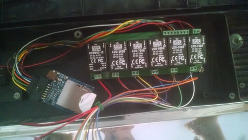
__________________
- Leon (aka - Water Dog) Deep Blue 57 Edge ATI Acro Garden Build Thread http://www.reefcentral.com/forums/showthread.php?p=25573384#post25573384 Current Tank Info: DeepBlue 57 Edge |
|
|
|
|
06/11/2018, 10:26 AM
|
#44 | |
|
Got Reef
Join Date: Mar 2006
Location: Weeki Wachee, Florida
Posts: 2,501
|
Quote:
__________________
Tom No matter how much you try to push the envelope, it remains stationary. |
|
|
|
|
|
06/11/2018, 10:31 AM
|
#45 | |
|
Got Reef
Join Date: Mar 2006
Location: Weeki Wachee, Florida
Posts: 2,501
|
Quote:
__________________
Tom No matter how much you try to push the envelope, it remains stationary. |
|
|
|
|
|
06/11/2018, 10:37 AM
|
#46 |
|
Registered Member
Join Date: Feb 2003
Location: Fairfield, CT
Posts: 1,516
|
I would imagine that jumper wires would work. If you look at my photo, you see along the bottom are the connections to the LEDs and fan. The connections on the upper left are the connections for the ribbon cable wires (that I linked to earlier) to the Bluefish Mini. The connections to the upper right are the (+, -) to the power supply. I would think that all of the connections across the top in my photo could be daisy chained with jumper wires. I’m sure Dave can easily walk you through the process.
__________________
- Leon (aka - Water Dog) Deep Blue 57 Edge ATI Acro Garden Build Thread http://www.reefcentral.com/forums/showthread.php?p=25573384#post25573384 Current Tank Info: DeepBlue 57 Edge |
|
|
|
|
06/11/2018, 11:58 AM
|
#47 | |
|
Registered Member
Join Date: Apr 2013
Posts: 1,793
|
Quote:
 Still wondering if the BF mini outputs enough current .. |
|
|
|
|
|
06/11/2018, 03:35 PM
|
#48 |
|
Got Reef
Join Date: Mar 2006
Location: Weeki Wachee, Florida
Posts: 2,501
|
oreo - Sorry 'bout that... You're right, I'd seen it. Problem is, at my age sometimes things get a little lost.

__________________
Tom No matter how much you try to push the envelope, it remains stationary. |
|
|
|
|
06/11/2018, 03:49 PM
|
#49 | |
|
Registered Member
Join Date: May 2008
Location: Melb, Vic, AU
Posts: 137
|
Quote:
|
|
|
|
|
|
06/11/2018, 03:58 PM
|
#50 |
|
Got Reef
Join Date: Mar 2006
Location: Weeki Wachee, Florida
Posts: 2,501
|
I haven't been able to find one.
__________________
Tom No matter how much you try to push the envelope, it remains stationary. |
|
|
|
 |
|
|


