
|
|
|
|||||||
 |
| Thread Tools |
 02/27/2015, 02:50 PM
|
#3151 |
|
Registered Member

Join Date: Oct 2008
Location: San Diego
Posts: 121
|
I would think so too, maybe i will break out the multimeter and test what amperage two together are really using. I just hooked it up to see how loud this silent fan was, and i am pretty impressed, i had to hold my ear close enough that the fan hit my cheek before i could really hear it. Of course these china box leds are running and it makes it hard to hear anything in the house.
|

|

|
|
02/27/2015, 07:28 PM
|
#3152 | |
|
Registered Member
Join Date: Aug 2011
Location: "The Land of Fruits & Nuts"
Posts: 879
|
Quote:
This design is panelized to include two adapters per 45mm X 32mm PcB. Use the 50mm X 50mm size option when ordering and you'll get two adapters for the price of one. I recommend using Seeedstudios, since their PcB ordering system is very user friendly.http://www.seeedstudio.com/service/index.php?r=pcb  
__________________
I love the smell of molten solder in the morning. |
|
|
|
|
|
02/27/2015, 09:30 PM
|
#3153 |
|
Registered Member
Join Date: Oct 2008
Location: San Diego
Posts: 121
|
Awesome! Thanks again O2!
|
|
|
|
|
03/02/2015, 08:04 AM
|
#3154 | |
|
Registered Member
Join Date: Dec 2012
Posts: 360
|
Quote:
The 05 will probably work, but the 08 will work better and probably for a longer time. |
|
|
|
|
|
03/02/2015, 03:24 PM
|
#3155 | |
|
Registered Member
Join Date: Oct 2008
Location: San Diego
Posts: 121
|
Quote:
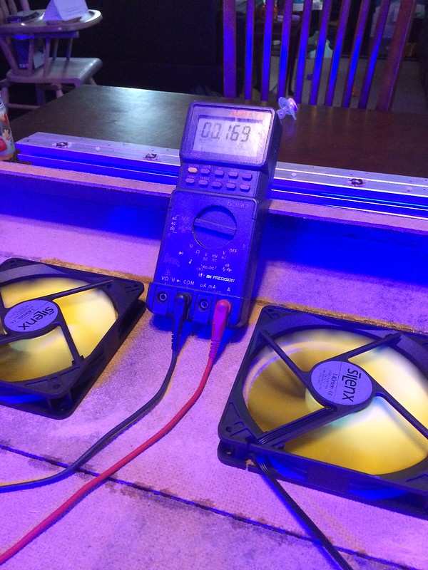 When first connected the highest in rush amperage i saw was .223A. It was hard to take a picture at the exact instance i connected the power but this was pretty close. I don't think my multimeter has a peak hold option. 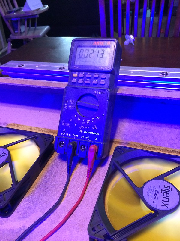 I will still order the swc 08 version just in case the fans ever get changed in the future and these aren't available. Looks like mouser is the only place that has the 08 versions available right now. |
|
|
|
|
|
03/15/2015, 03:25 PM
|
#3156 |
|
Registered Member
Join Date: Dec 2010
Posts: 14
|
I've been using a 10 LED strand (cree XT-Es) with a LDD-700HW for years now with no issues. I added a second LED strand today and now neither power up
 I tested all the LEDs with batteries and they all power up and all my connections are good so I fear I have somehow fried both LDDs. I have tried swapping the LDDs around and still nothing from either strand. No shorts or anything and I measure 48V across the input terminals and about 50mv across the output terminals of the LDD. I tested all the LEDs with batteries and they all power up and all my connections are good so I fear I have somehow fried both LDDs. I have tried swapping the LDDs around and still nothing from either strand. No shorts or anything and I measure 48V across the input terminals and about 50mv across the output terminals of the LDD.I'm using a 48V 1.8A PS and was using PWM but now for testing I have the PWM line unconnected and only powering the original strand of LEDS. Here is what I had wired originally (only 2 strands) but now I have the white line unconnected. Any help would be appreciated, if I have somehow killed the LDDs I don't want to order more and kill those too! |
|
|
|
|
03/15/2015, 05:38 PM
|
#3157 | |
|
LED world domination!
Join Date: Jan 2012
Location: Okeechobee, FL
Posts: 1,030
|
Quote:
__________________
Dinoflagellates are the kiss of death. Current Tank Info: Acquasole 60, IceCap 15 Sump, 2x Maxspect Ethereal, Coral Box D500 skimmer, Maxspect Gyre 150, Jecod DCS-5000 |
|
|
|
|
|
03/15/2015, 06:26 PM
|
#3158 | |
|
Registered Member
Join Date: Dec 2010
Posts: 14
|
Quote:
Since my last post I tried a different power supply and connected them to only 1 LED to eliminate any variables but still no go. I'm probably going to go with the LDD boards to replace these but I really don't know how I killed 2 working LDDs Besides doing something really stupid like wiring them backwards what else can kill these things?
|
|
|
|
|
|
03/15/2015, 08:52 PM
|
#3159 |
|
Registered Member
Join Date: May 2011
Location: New York
Posts: 585
|
LDD VIN should be in parallel. Both (+) of LDDs to PS (+). Both (-) of LDDs to PS (-).
__________________
Since May 2011: OLD: 57G rimless NOW: ELOS 120, DIY LED using reefll.com 12-up boards |
|
|
|
|
03/16/2015, 06:00 AM
|
#3160 | |
|
Registered Member
Join Date: Dec 2010
Posts: 14
|
Quote:
Oh well hopefully I'll figure out the problem before the replacements arrive 
|
|
|
|
|
|
03/16/2015, 08:14 AM
|
#3161 |
|
Registered Member
Join Date: Dec 2012
Posts: 360
|
If you turned on the power to the LDD's without the LEDs hooked up then you probably fried them. They must have a load connected to the output when they are powered on or they burn up almost instantly. I would bet they are dead. Krazie

|
|
|
|
|
03/23/2015, 01:19 PM
|
#3162 |
|
Registered Member
Join Date: Jun 2011
Location: Port Alberni, B.C., Canada
Posts: 895
|
Sorry for double posting this, but I'm trying to get this thing fired up and it's one of the last things I've got to do and after today, I'm busy with work again and won't be able to get to it for a while. I seen a couple of you are on line so I thought I'd put this in here too..
I'm totally brain farting. I built my controller based on the Jarduino sketch. All my strings are running on LDD boards but 1 of my LED strings are hooked onto a HLG-185H-42B and one to a HLG-185H-36B. Those are the ones I'm screwed up on. The LED's are in series hooked onto the V- and V+ For the life of me I'm second guessing where the Dim+ and Dim- wires go. I thought the Dim+ went to my PWM control pin on the Arduino but nothing comes to mind for the Dim-. Does it get hooked to the ground plane of the Arduino board? ARGH! I think I'm losing my mind...
__________________
130 lbs Tonga LR, GFO and Carbon reactors, Tunze ozmolator ATO, 2- 20 gal QT tanks, Current Tank Info: 80 gal display 48L X 24H X16D, 2 MP-40's, Odyssea 2-250W MH 4-HO T-5 Actinic's, 80 lbs Aragonite sand, 4 - 150W titanium heaters, Reeflo Baracuda return pump, 150gal sump, Filter Guys Reef Miser 6 stage + 1 Dual RO/DI, LifeReef 48" Skimmer |
|
|
|
|
03/23/2015, 01:28 PM
|
#3163 |
|
LED world domination!
Join Date: Jan 2012
Location: Okeechobee, FL
Posts: 1,030
|
Common ground, so on your power supply.
Also, the HLG are 10v, not 5v, so you'll need to convert the output from the Arduino.
__________________
Dinoflagellates are the kiss of death. Current Tank Info: Acquasole 60, IceCap 15 Sump, 2x Maxspect Ethereal, Coral Box D500 skimmer, Maxspect Gyre 150, Jecod DCS-5000 |
|
|
|
|
03/23/2015, 02:01 PM
|
#3164 |
|
Registered Member
Join Date: Dec 2012
Posts: 360
|
Yup, What ^^ he said.

|
|
|
|
|
03/23/2015, 03:06 PM
|
#3165 | ||
|
Registered Member
Join Date: Jun 2011
Location: Port Alberni, B.C., Canada
Posts: 895
|
Quote:
Quote:
Will it work at all on 5V or will it just not run at full power? I also read somewhere that the PWM on an Arduino runs from 0-255 or off to 100% but some Meanwells are backwards? So off is 255 or 0% and full on 100% is 0. Does that make sense? Hmmm, now I have to figure that out, lol. Sometimes the internet is the enemy of useful knowledge... so much seemingly contradictory info if you don't have a working knowledge of something
__________________
130 lbs Tonga LR, GFO and Carbon reactors, Tunze ozmolator ATO, 2- 20 gal QT tanks, Current Tank Info: 80 gal display 48L X 24H X16D, 2 MP-40's, Odyssea 2-250W MH 4-HO T-5 Actinic's, 80 lbs Aragonite sand, 4 - 150W titanium heaters, Reeflo Baracuda return pump, 150gal sump, Filter Guys Reef Miser 6 stage + 1 Dual RO/DI, LifeReef 48" Skimmer |
||
|
|
|
|
03/23/2015, 04:55 PM
|
#3166 | |
|
Registered Member
Join Date: Sep 2009
Posts: 1,079
|
Quote:
|
|
|
|
|
|
03/23/2015, 05:25 PM
|
#3167 | |
|
Registered Member
Join Date: Mar 2005
Location: St. Louis, MO.
Posts: 3,259
|
Quote:
Otherwise if using the HLG to run and dim the strings (No LDD drivers on those two) then as others said you will need to convert the arduino 5v pwm into a 0-10v PWM signal. |
|
|
|
|
|
03/23/2015, 09:05 PM
|
#3168 | |
|
Registered Member
Join Date: Apr 2013
Posts: 1,793
|
Quote:
AFAICT Meanwells aren't "backwards" Drivers like buckpucks are backwards.. 10-0V dimming.. Yes you have 0-10V or 10V PWM You need to do like the Typhon (but maybe better..) You need to convert the 5V PWM to 10V PWM. @5V it will either not work or just go to 50% at 100% duty cycle.. 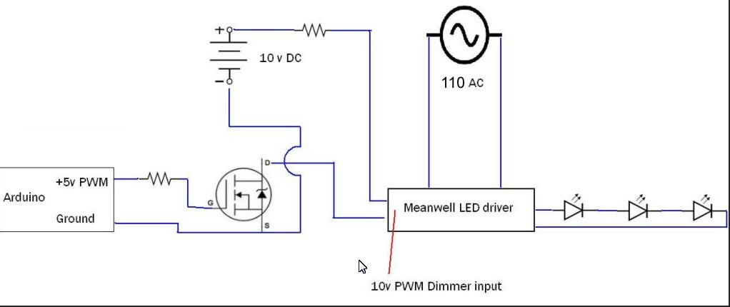 http://forum.allaboutcircuits.com/th...10v-pwm.69870/ OR convert the 5V PWM to 0-10V out.. http://www.nano-reef.com/topic/21811...=arduino+0-10v your mixing of dimming types (and drivers) is a bit problematic.. O2 may have some conversion boards laying around to stick on the 5V pins you want to use for the 2 oddball (in the LDD sense) drivers.. OR just update your power supply and drivers to match.. NOTE: Ideas of "concept" not actual use... Last edited by oreo57; 03/23/2015 at 09:35 PM. |
|
|
|
|
|
03/23/2015, 09:44 PM
|
#3169 | |
|
Registered Member
Join Date: Aug 2011
Location: "The Land of Fruits & Nuts"
Posts: 879
|
Quote:
Yep! Just make sure the controller's PWM frequency is 25khz or so to eliminate that annoying buzzing noise that comes with using PWM on conventional cooling fans.
__________________
I love the smell of molten solder in the morning. |
|
|
|
|
|
03/23/2015, 09:57 PM
|
#3170 | ||||
|
Registered Member
Join Date: Jun 2011
Location: Port Alberni, B.C., Canada
Posts: 895
|
Quote:
But another set of NW and CW I got XM-L's that run at a fV of 3.35 @ 3000mA so I went with the HLG's to drive them. With all I got going on, that might be total overkill and only being able to run them at 50% may not be a bad thing IF that will work. My tank is a 210 - so 30" deep and I was originally worried I might not have enough punch to get to the bottom with the XT-E's on the 3up stars. Quote:
Quote:
 Quote:
O2, I'll PM ya just in case this misses ya, but have you made some conversion boards that you have extra of? I am using your boards already for my LDD drivers that I got made when I first started this project back a couple years a go I think it was. Thanks guys for the help, I REALLY appreciate it.
__________________
130 lbs Tonga LR, GFO and Carbon reactors, Tunze ozmolator ATO, 2- 20 gal QT tanks, Current Tank Info: 80 gal display 48L X 24H X16D, 2 MP-40's, Odyssea 2-250W MH 4-HO T-5 Actinic's, 80 lbs Aragonite sand, 4 - 150W titanium heaters, Reeflo Baracuda return pump, 150gal sump, Filter Guys Reef Miser 6 stage + 1 Dual RO/DI, LifeReef 48" Skimmer |
||||
|
|
|
|
03/23/2015, 10:16 PM
|
#3171 | |
|
Registered Member
Join Date: Apr 2013
Posts: 1,793
|
Quote:
another fun way is to just hook a 9V battery to the 10V line.. NO shared grounds w/ that and full on.. well 9V on..  Hmm a small lithium button cell could run at 40% for a long time I believe Just for fun..again don't ground the battery to anything.. Manual on/off of course.. A 5V ps hooked directy to the dim circuit on a timer would give you 50% as well There are numerous ways to bypass the Adruino w/ those 2 drivers.. A commercial converter: http://www.newegg.com/Product/Produc...g&gclsrc=aw.ds 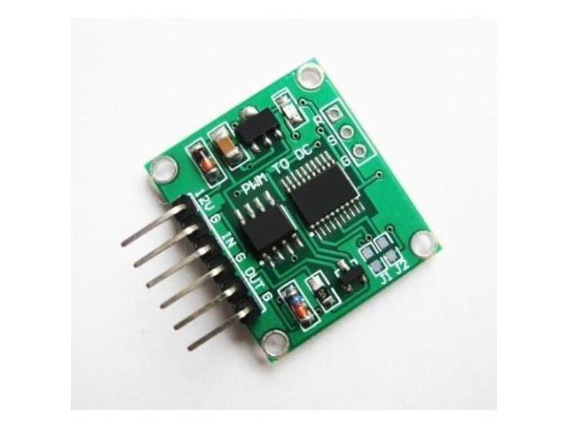
Last edited by oreo57; 03/23/2015 at 10:23 PM. |
|
|
|
|
|
03/24/2015, 02:53 PM
|
#3172 |
|
Registered Member
Join Date: Jun 2011
Location: Port Alberni, B.C., Canada
Posts: 895
|
Thanks guys
I've ordered up one of Coralux's converter's.
__________________
130 lbs Tonga LR, GFO and Carbon reactors, Tunze ozmolator ATO, 2- 20 gal QT tanks, Current Tank Info: 80 gal display 48L X 24H X16D, 2 MP-40's, Odyssea 2-250W MH 4-HO T-5 Actinic's, 80 lbs Aragonite sand, 4 - 150W titanium heaters, Reeflo Baracuda return pump, 150gal sump, Filter Guys Reef Miser 6 stage + 1 Dual RO/DI, LifeReef 48" Skimmer |
|
|
|
|
03/24/2015, 03:17 PM
|
#3173 | |
|
Registered Member
Join Date: Apr 2013
Posts: 1,793
|
Quote:
i thought you needed a few for some LDD's to stay "native" 5V PWM Out of curiosity did you pick 10V analog or 10V PWM? |
|
|
|
|
|
03/24/2015, 04:58 PM
|
#3174 |
|
Registered Member
Join Date: Jun 2011
Location: Port Alberni, B.C., Canada
Posts: 895
|
If I plug the terminal strip straight into the Arduino board, yea, it will convert all, but I'll just mount it somewhere in my project box and run jumpers to the 2 PWM pins on the board to the converter.
I ended up getting the 10V PWM - for some reason I thought I remember reading way back when that PWM is the only way I'll get it to dim to 0. Although I'll only have them coming on for 3-4 hours a day max, so for these 2 strings dimming to 0 isn't as big a deal as say the RB's.
__________________
130 lbs Tonga LR, GFO and Carbon reactors, Tunze ozmolator ATO, 2- 20 gal QT tanks, Current Tank Info: 80 gal display 48L X 24H X16D, 2 MP-40's, Odyssea 2-250W MH 4-HO T-5 Actinic's, 80 lbs Aragonite sand, 4 - 150W titanium heaters, Reeflo Baracuda return pump, 150gal sump, Filter Guys Reef Miser 6 stage + 1 Dual RO/DI, LifeReef 48" Skimmer |
|
|
|
|
03/24/2015, 06:06 PM
|
#3175 | |
|
Registered Member
Join Date: Apr 2013
Posts: 1,793
|
Quote:
and thanks, I didn't know they had that board.. |
|
|
|
|
|
|
|


