
|
|
|
|||||||
 |
| Thread Tools |
 03/16/2012, 11:52 PM
|
#1026 |
|
Registered Member
Join Date: Mar 2012
Location: Kingwood, Texas
Posts: 32
|
Jarek, I'm getting the same error. I hope it's fixed soon.
 Sammy, that's a real nice box! |

|

|
|
03/17/2012, 08:10 AM
|
#1027 | |
|
Registered Member
Join Date: Jul 2007
Location: Puerto Rico
Posts: 673
|
Quote:
|
|
|
|
|
|
03/17/2012, 08:50 PM
|
#1028 | |
|
Registered Member
Join Date: Aug 2007
Location: Gurabo, PR USA
Posts: 75
|
Quote:
Last edited by mm.reefs; 03/17/2012 at 09:00 PM. |
|
|
|
|
|
03/19/2012, 08:38 AM
|
#1029 | |
|
Registered Member
Join Date: Feb 2011
Posts: 70
|
Quote:
Also... have you ever considered making your own pcb's? http://www.youtube.com/watch?v=nnzdS3l60Wo http://www.youtube.com/watch?v=wKEe3otWstM http://www.instructables.com/id/DIY-...ble-Etch-Tank/ And instead of using an iron to transfer the black ink to the copper, I've read of people using laminating machines... http://www.bot-thoughts.com/2009/08/...b-etching.html You'd obviously need to design for a "single-sided" board, just need to use jumpers so not to cross traces. In the long run.. it would be cheaper than ordering from a pcb house. |
|
|
|
|
|
03/19/2012, 08:54 AM
|
#1030 |
|
Registered Member
Join Date: Mar 2012
Location: Kingwood, Texas
Posts: 32
|
I'm pretty new at this. I've got the Modern Device USB-BUB II, and I'm having trouble finding a driver for it. I'm using a machine running Windows 7. Also, there are two 3 pin headers with jumpers, how do these jumpers need to be placed? I've found some examples for the regular BUB, but not the BUB II.
Thanks. |
|
|
|
|
03/19/2012, 10:06 AM
|
#1031 | |
|
Team RC Member
Join Date: Sep 2003
Location: NY
Posts: 17,749
|
From the product page:
Quote:
The BUB uses the ultra-common FTDI chip, so it should use the same driver as any other FTDI device (i.e. older Arduino boards, BUB I, FTDI cables, etc). I've never used it on Win7 so I can't really give you a direct answer.
__________________
Inconveniencing marine life since 1992 "It is my personal belief that reef aquaria should be thriving communities of biodiversity, representative of their wild counterparts, and not merely collections of pretty specimens growing on tidy clean rock shelves covered in purple coralline algae." (Eric Borneman) |
|
|
|
|
|
03/19/2012, 05:53 PM
|
#1032 |
|
Registered Member
Join Date: Mar 2012
Location: Kingwood, Texas
Posts: 32
|
I'll have to try it on my other machine then. When I plug it in, the LEDs flash once, and then nothing happens (other than the usual beep that it makes when I plug a phone into it to charge it). If I put jumpers on it, the lights stay on, and the computer says hardware is detected but cannot find device drivers. So I'll give it a shot on my other machine with XP.
|
|
|
|
|
03/20/2012, 08:35 AM
|
#1033 |
|
Team RC Member
Join Date: Sep 2003
Location: NY
Posts: 17,749
|
Yeah, sorry I can't help without direct experience with that version of the BUB. I actually lost my original BUB a few weeks ago so I just bought the lilypad FTDI breakout.
__________________
Inconveniencing marine life since 1992 "It is my personal belief that reef aquaria should be thriving communities of biodiversity, representative of their wild counterparts, and not merely collections of pretty specimens growing on tidy clean rock shelves covered in purple coralline algae." (Eric Borneman) |
|
|
|
|
03/20/2012, 10:48 AM
|
#1034 |
|
Registered Member
Join Date: Mar 2012
Location: Kingwood, Texas
Posts: 32
|
It must be a Windows 7 issue. I just plugged the BUB II into my XP machine, and it detected the device and installed 2 driver files without a lick. And I can't even get that machine to surf the internet right now (even though it has both functioning wired and wireless connections... Norton won't even open, yet something else I have to tinker with.... :/
|
|
|
|
|
03/20/2012, 10:33 PM
|
#1035 |
|
Registered Member
Join Date: Jun 2009
Location: Wethersfield, CT
Posts: 375
|
I'm looking for little help with my temp sensor (hookup and coding)
I've found a temp sensor on modern device http://shop.moderndevice.com/product...erature-sensor Here is the sketch for it, /*TMP37.pde * Arduino Sketch to read a TMP37 Temperature Sensor * Paul Badger * 2010 * Sensor works between 5 degrees & 100 degrees C * 20 mV / degree C * Can be used with TMP35 & TMP36 by changing voltsPerDegree */ float voltsPerDegree = 0.02; // change to 0.01 for TMP35 & 36 void setup() { Serial.begin(9600); } void loop() { int sensorValue; float volts; float celsius; float farenheit; sensorValue = analogRead(0); volts = sensorValue * 5.0 / 1024.0; // convert AD units to volts // convert volts to celsius celsius = (sensorValue * 5.0 / 1024.0) / voltsPerDegree; // standard conversion from celsius to farenheit farenheit = (((sensorValue * 5.0 / 1024.0) / voltsPerDegree) * 9.0 / 5.0) + 32; Serial.print(sensorValue, DEC); Serial.print(" A/D units "); Serial.print(volts); Serial.print(" volts "); Serial.print(celsius); Serial.print(" degrees C "); Serial.print(farenheit); Serial.println(" degrees F"); } Which i have tested on BBB from modern device and it shows temp of the probe via the serial port on ardunio. I"ve soldered wires to each leg and shrink wrapped each leg individually so there is no possibility of shorting anything out when attached to heat sink. So far so good. Well next is the hard part for me. This part sensorValue = analogRead(0); If I was to attach the temp probe to the serial port on Typhoon, what do I put in for the input port/pin instead of the (0) part The next problem for me is replacing all the lines of serial.print with some sort of LCD.print command to actually display the temp on the typhoon. I would only need the deg F line to print . Hope that is not too much to ask
|
|
|
|
|
03/21/2012, 07:20 AM
|
#1036 | ||
|
Team RC Member
Join Date: Sep 2003
Location: NY
Posts: 17,749
|
Quote:
If you do have an earlier version of the hardware, you can "greenwire" it by soldering directly to the pad for A3 on the AVR. A3 is not connected to anything so it's available, but this will be a bit awkward. Quote:
__________________
Inconveniencing marine life since 1992 "It is my personal belief that reef aquaria should be thriving communities of biodiversity, representative of their wild counterparts, and not merely collections of pretty specimens growing on tidy clean rock shelves covered in purple coralline algae." (Eric Borneman) |
||
|
|
|
|
03/21/2012, 07:35 AM
|
#1037 |
|
Team RC Member
Join Date: Sep 2003
Location: NY
Posts: 17,749
|
What do you all think about the 16x2 screen currently used on the Typhon? If we're making a newer, better version should we stay with that screen size or go to something larger, i.e. 20x4? It would allow much nicer menus and more info on the "home" screen, but it would bump the price by maybe $5-$7.
__________________
Inconveniencing marine life since 1992 "It is my personal belief that reef aquaria should be thriving communities of biodiversity, representative of their wild counterparts, and not merely collections of pretty specimens growing on tidy clean rock shelves covered in purple coralline algae." (Eric Borneman) |
|
|
|
|
03/21/2012, 09:18 PM
|
#1038 |
|
Registered Member
Join Date: Jun 2009
Location: Wethersfield, CT
Posts: 375
|
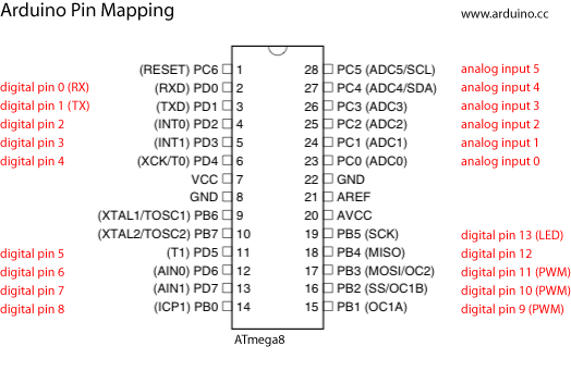 I do have the pre 1.0 so i'll have to "greenwire" Just to make sure, the analog pin 3 is the one marked 26 , PC3 (ADC3) on the picture above. To which i can solder the temp sensor? Thanks! I had one of the early sketches that did not show date, just time, so i thought there was room on the home screen. And i'm for bigger screen if it fits, (i think i even have one laying around) |
|
|
|
|
03/21/2012, 09:21 PM
|
#1039 |
|
Registered Member
Join Date: Mar 2012
Location: Kingwood, Texas
Posts: 32
|
To me, I wouldn't mind a few more dollars for a larger display.
|
|
|
|
|
03/21/2012, 09:32 PM
|
#1040 |
|
Registered Member
Join Date: Jan 2009
Location: Palmdale
Posts: 2,556
|
Well... The bigger screen would be nice.. But Maybe there should be a point where a new thread/controller project is started.. Well i dont know.. its still going to be a basic controller, which is what you kind of had in mind for this project. I think.. So, bigger is better, but def not necessary. I think you know where im going here. On second thought.. this is just basically a revision of the intitial project with a few new features added. enough rambling...
__________________
~SFVR Member~ 125 Gal Long/50 Gal sump, 2xMP40QD,Aquamax CONES CO-03/Speed Wave dc return 4x AI Sol Blues/Director + 2 80w T5 retrofit/Apex Controller Current Tank Info: 125 gal 72X18X22 |
|
|
|
|
03/22/2012, 06:59 AM
|
#1041 | |
|
Registered Member
Join Date: Jul 2011
Posts: 118
|
Quote:
Typhon ][ Basic controller? |
|
|
|
|
|
03/22/2012, 08:40 AM
|
#1042 | ||
|
Team RC Member
Join Date: Sep 2003
Location: NY
Posts: 17,749
|
Quote:
Quote:
__________________
Inconveniencing marine life since 1992 "It is my personal belief that reef aquaria should be thriving communities of biodiversity, representative of their wild counterparts, and not merely collections of pretty specimens growing on tidy clean rock shelves covered in purple coralline algae." (Eric Borneman) |
||
|
|
|
|
03/22/2012, 11:30 AM
|
#1043 |
|
Registered Member
Join Date: Aug 2001
Location: California
Posts: 2,259
|
I'm for a larger screen if possible.
In fact, I'm actually up for making two of these now since we have two LED retrofitted Bio-cubes in the house. It would be a lot easier to manage the LED's using the PWM input instead of instant On/Off. I'd love a temp and some other options but not sure how possible it is. Building the LED and doing the retro fit work wasn't bad. Designing or adding to a base circuit board is another thing all together. So I'm trying to leverage something that is already done rather than buying another Neptune type controller at that price (3 kids in college!). Mean Well power supplies is used by the one (via Rapid) and the other tank uses Steve's with his drivers - not sure what either of those are actually but they are holding up well and have good color. Is it possible to go in on the next revision of boards with someone once ready?
__________________
-saf1 Current Tank Info: 210 gallon mixed reef |
|
|
|
|
03/22/2012, 06:25 PM
|
#1044 | |
|
Registered Member
Join Date: Jun 2009
Location: Wethersfield, CT
Posts: 375
|
Quote:
Yes i was planing on soldering to the socket on the bottom side. And also thought about using some sort of mini connection socket or some such. And also correct of GNG and +5v, I should be able to find something with 5v on the board somewhere to attach it to. On the other hand, modern device has another temp sensor that is i2c compatible, http://shop.moderndevice.com/product...erature-sensor but i'm not sure how to make that work yet. Baby steps first
|
|
|
|
|
|
03/23/2012, 07:20 AM
|
#1045 |
|
Team RC Member
Join Date: Sep 2003
Location: NY
Posts: 17,749
|
Wow, somehow I'd missed that sensor to date. It looks really amazing. I2C is my favorite bus for this stuff and it has very good resolution.
__________________
Inconveniencing marine life since 1992 "It is my personal belief that reef aquaria should be thriving communities of biodiversity, representative of their wild counterparts, and not merely collections of pretty specimens growing on tidy clean rock shelves covered in purple coralline algae." (Eric Borneman) |
|
|
|
|
03/23/2012, 11:27 PM
|
#1046 |
|
Registered Member
Join Date: Jan 2009
Location: Palmdale
Posts: 2,556
|
stupid question.. I bought according to your BOM, the battery holder has dowel pins on the bottom and keeps it raised up.. i can still solder the leads. is this intentional?
__________________
~SFVR Member~ 125 Gal Long/50 Gal sump, 2xMP40QD,Aquamax CONES CO-03/Speed Wave dc return 4x AI Sol Blues/Director + 2 80w T5 retrofit/Apex Controller Current Tank Info: 125 gal 72X18X22 |
|
|
|
|
03/24/2012, 10:38 AM
|
#1047 | ||
|
Registered Member
Join Date: Feb 2011
Posts: 70
|
Quote:
Quote:
|
||
|
|
|
|
03/26/2012, 07:36 AM
|
#1048 | |
|
Registered Member
Join Date: Mar 2012
Location: Kingwood, Texas
Posts: 32
|
Quote:
On another note, I went to the FTDI website and downloaded the drivers for windows 7, and it appears to be fine now. Now I'm just waiting for my PCBs to show up. 
|
|
|
|
|
|
03/26/2012, 01:20 PM
|
#1049 |
|
Registered Member
Join Date: Jan 2009
Location: Palmdale
Posts: 2,556
|
I finally got mine built. Uploaded the sketch, Took forever... For those who try this, just download .22 arduino ide, and The old buttons library, and eepromvar. Put them in the librarys folder in the arduino folders. open the arduino program. find the typhoon.pde you downloaded and then verify it. It should compile good. then upload it.
Ok so my select and +- buttons work fine.. all other menus, i can set start time/stop time, duration fade etc etc.. except to set the time. I push + - and select and nothing happens. I dont have a battery yet, but i wouldnt think this would affect it..
__________________
~SFVR Member~ 125 Gal Long/50 Gal sump, 2xMP40QD,Aquamax CONES CO-03/Speed Wave dc return 4x AI Sol Blues/Director + 2 80w T5 retrofit/Apex Controller Current Tank Info: 125 gal 72X18X22 |
|
|
|
|
03/26/2012, 01:37 PM
|
#1050 |
|
Team RC Member
Join Date: Sep 2003
Location: NY
Posts: 17,749
|
If you don't have a batter the RTC is probably not functioning correctly. It won't operate without SOMETHING there. If you want to run it without a battery, put a bit of bare wire or something else conductive in the battery holder to short out the leads. Most of the time they'll run like this (though of course you'll loose memory when it loses power).
pandimus, that's the way the battery clip is designed to operate. I used that clip as a holdover from when I designed the Hydra. On that design there were other components/pads UNDER the battery so we needed it raised up. On this design that isn't the case. In version 2 of the Typhon I'm using a different clip, fwiw. Speaking of version two, what do people think about the FTDI chip being onboard? It would mean you would not need a separate FTDI breakout to program the device, but it would bump the price up by ~$5. Right now, I'm thinking I may put the parts in the design, along with a header for the serial port (as there is now) which would let people choose. If you wanted it onboard, buy the parts and solder them in. If you already have a cable or BUB or other breakout, leave the parts off and just plug your breakout into the header. What do people think of this?
__________________
Inconveniencing marine life since 1992 "It is my personal belief that reef aquaria should be thriving communities of biodiversity, representative of their wild counterparts, and not merely collections of pretty specimens growing on tidy clean rock shelves covered in purple coralline algae." (Eric Borneman) |
|
|
|
|
|
|
 Similar Threads
|
||||
| Thread | Thread Starter | Forum | Replies | Last Post |
| Cheap Moonlight | ticklesworth | New to the Hobby | 3 | 04/04/2010 04:09 PM |
| Cheap Moonlight | ticklesworth | Do It Yourself |
0 | 04/03/2010 08:52 AM |
| Arduino base controller - power pack ONLY TODAY | MaLi | Do It Yourself |
0 | 03/07/2010 05:56 AM |
| Sumps 101: Cheap, simple and effective for small tanks | cody6766 | Central Oklahoma Marine Aquarium Society | 8 | 01/06/2009 10:57 AM |


