
|
|
 03/16/2015, 10:47 AM
|
#76 |
|
Registered Member
Join Date: Mar 2015
Location: Midwest, USA
Posts: 15
|
Wow, awesome build. Been immersing myself in all the DIY LED threads, and there are so many options to choose from. How long did it take to get the PCB's? Also what was the minimum order?
|

|

|
|
03/16/2015, 12:45 PM
|
#77 |
|
100-mile-commuter
Join Date: Dec 2004
Location: almost nevada
Posts: 4,721
|
The metal core PCBs were here after about 7 calendar days - pricing was by sq-inches (increments of 50/100/150 sqinch) - the more you order the cheaper it gets per unit of course.
The driver boards are from OSHpark, which takes a bit longer (about 1.5-2 weeks) but is a great way to get 3 boards at $2/sqinch.
__________________
Custom electronics purveyor. blueAcro.com Current Tank Info: 90g SPS+mixed reef (10 yrs): LEDBrick LEDs, 40g custom sump, Ca reactor, chiller, Vortech, lots of custom electronics |
|
|
|
|
03/16/2015, 07:48 PM
|
#78 |
|
Registered Member
Join Date: Mar 2015
Location: Midwest, USA
Posts: 15
|
Cool, thanks for the quick reply. Can't wait to see what other spectrums/combinations you think of.
|
|
|
|
|
04/26/2015, 09:50 PM
|
#79 |
|
100-mile-commuter
Join Date: Dec 2004
Location: almost nevada
Posts: 4,721
|
I finally found time to build a single copy of the driver board and start doing validation tests.
I used a similar paste + reflow construction technique due to the higher part count (I usually manually assemble one-offs, but this was faster in the end): Starting to populate parts 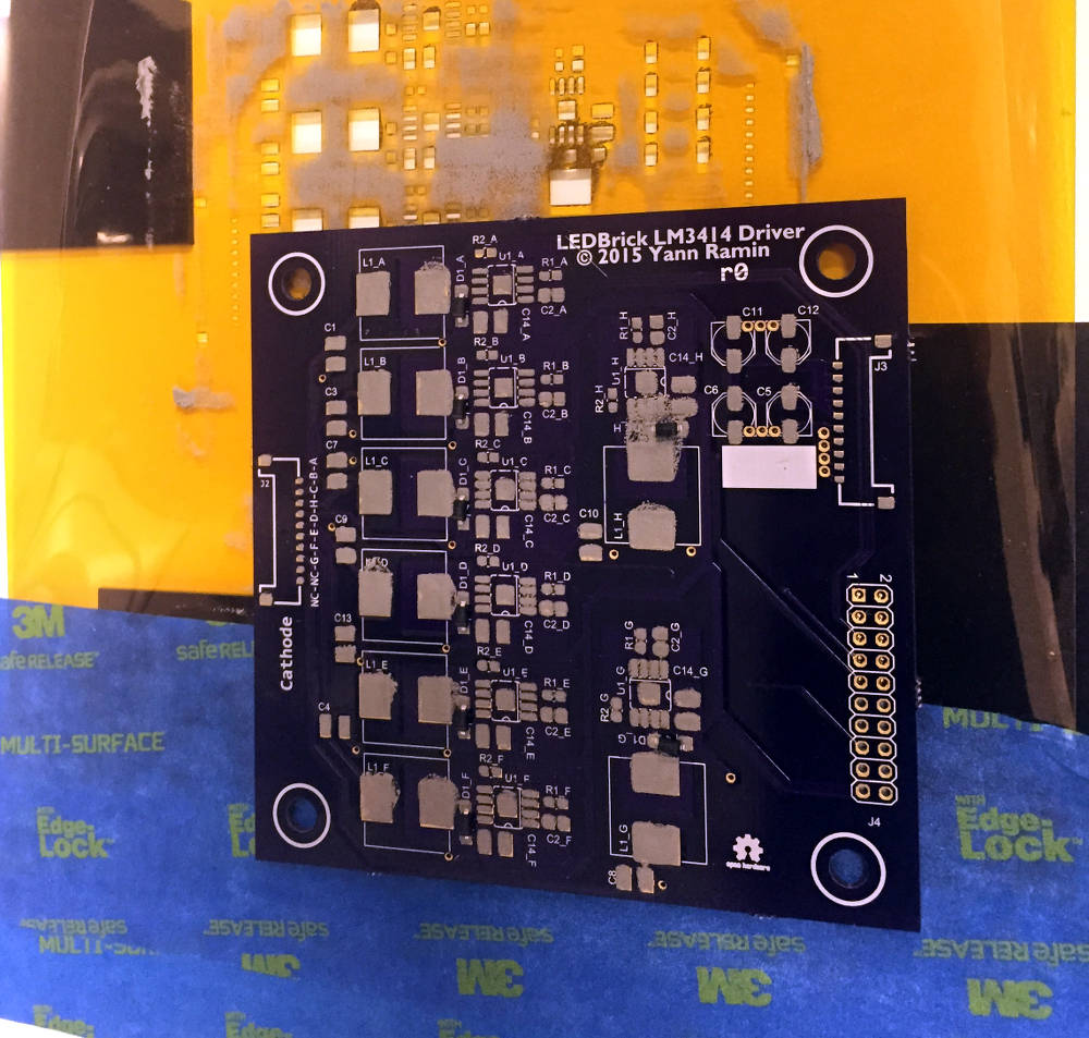 Several minutes later, magic, a complete board! 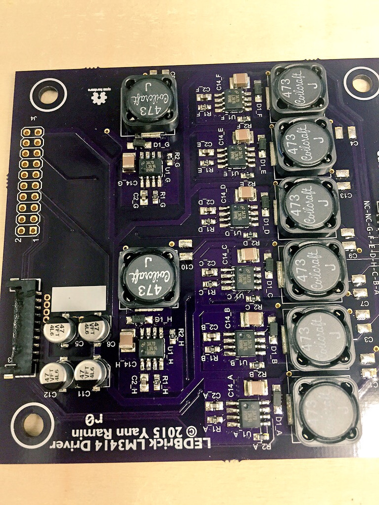 The average current output regulation is spot on (set to 500mA, within 1%). The switcher is running at 300kHz, which allows a lot of flexibility in the frequency of the PWM dimming signal. The driver appropriately cuts out when the PWM signal is brought to GND. Dimming works great without an output capacitor - I'm experimenting what the realistic ripple currents and ringing end up at. I haven't performed an efficiency calculation yet. 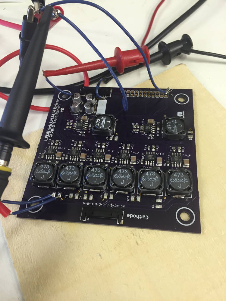
__________________
Custom electronics purveyor. blueAcro.com Current Tank Info: 90g SPS+mixed reef (10 yrs): LEDBrick LEDs, 40g custom sump, Ca reactor, chiller, Vortech, lots of custom electronics |
|
|
|
|
04/27/2015, 11:14 AM
|
#80 |
|
Registered Member
Join Date: Nov 2002
Location: Swartz Creek
Posts: 728
|
tagging along.
__________________
Just say no to CRABS! Current Tank Info: 85 Gallon mixed Reef. Halide/LED combo lighting. |
|
|
|
|
04/27/2015, 11:49 AM
|
#81 |
|
100-mile-commuter
Join Date: Dec 2004
Location: almost nevada
Posts: 4,721
|
If anyone is interested in boards ahead of any docs, I've shared them up on OSHPark:
https://oshpark.com/shared_projects/7uwwfspd Docs coming soon.
__________________
Custom electronics purveyor. blueAcro.com Current Tank Info: 90g SPS+mixed reef (10 yrs): LEDBrick LEDs, 40g custom sump, Ca reactor, chiller, Vortech, lots of custom electronics |
|
|
|
|
05/02/2015, 05:31 AM
|
#82 |
|
Registered Member
Join Date: Apr 2011
Posts: 53
|
This is really nice build, tagging along to see progresss
|
|
|
|
|
05/09/2015, 01:17 PM
|
#83 |
|
Registered Member
Join Date: Apr 2006
Location: Serbia
Posts: 4
|
LM3414 and driver board
First of all, thanks for sharing a design idea,
I was wondering, it would be nice to also share measurements of the driver board. On the original TI page: http://www.ti.com/product/lm3414 a couple of users not praising this driver. How is the chip performing on your board? I am having some doubts about this current-mirror tech without true sense resistor and feedback. If everything is ok, I would use this chip in conjunction with http://www.microchip.com/paramcharts...rects=digipots to digitally set max current per channel. Anyway, before I found out this chip on your design, I looked at lm3405/06, but again no digital max current set. But, there is one really interesting chip - LT3476, not from TI. Quad based, 1.5A, up to 36Vdc. The driver is using REAL sense resistor, only setting sense voltage. So, for the sake of trying out different solutions, it might be interesting for me to try this quad design ? Let us first wait and see your measurements. Specifically set current to measured current in different Vin. And also, power efficiency. |
|
|
|
|
07/13/2015, 09:31 AM
|
#84 | |
|
100-mile-commuter
Join Date: Dec 2004
Location: almost nevada
Posts: 4,721
|
Quote:
I need to do a full evaluation of efficiency at different operating points (as they are all running off of a 24V input, but have dramatically different Vfw on each channel), but rough measurements put this layout and design at > 90%.
__________________
Custom electronics purveyor. blueAcro.com Current Tank Info: 90g SPS+mixed reef (10 yrs): LEDBrick LEDs, 40g custom sump, Ca reactor, chiller, Vortech, lots of custom electronics |
|
|
|
|
|
07/13/2015, 12:19 PM
|
#85 |
|
100-mile-commuter
Join Date: Dec 2004
Location: almost nevada
Posts: 4,721
|
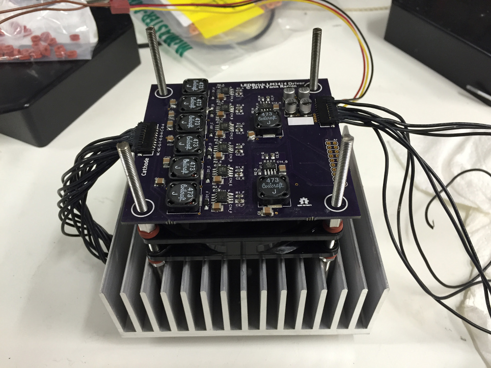
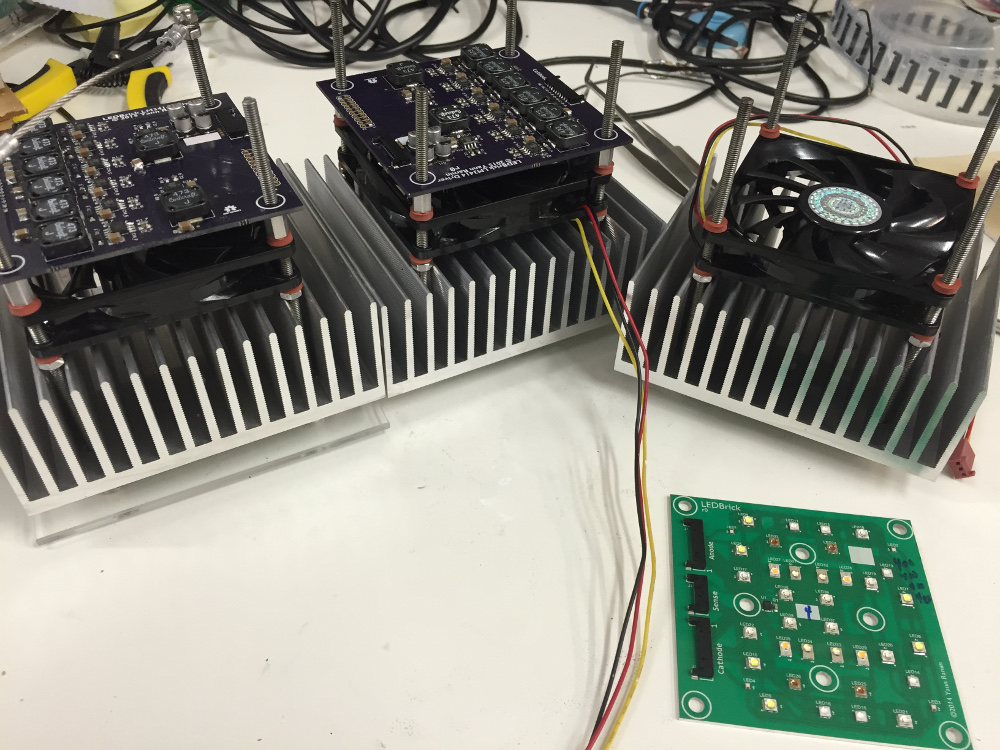
Finally, a complete driver + emitter build (so many other concurrent projects
 ) )All channels set to a 500mA limit. No external PWM. 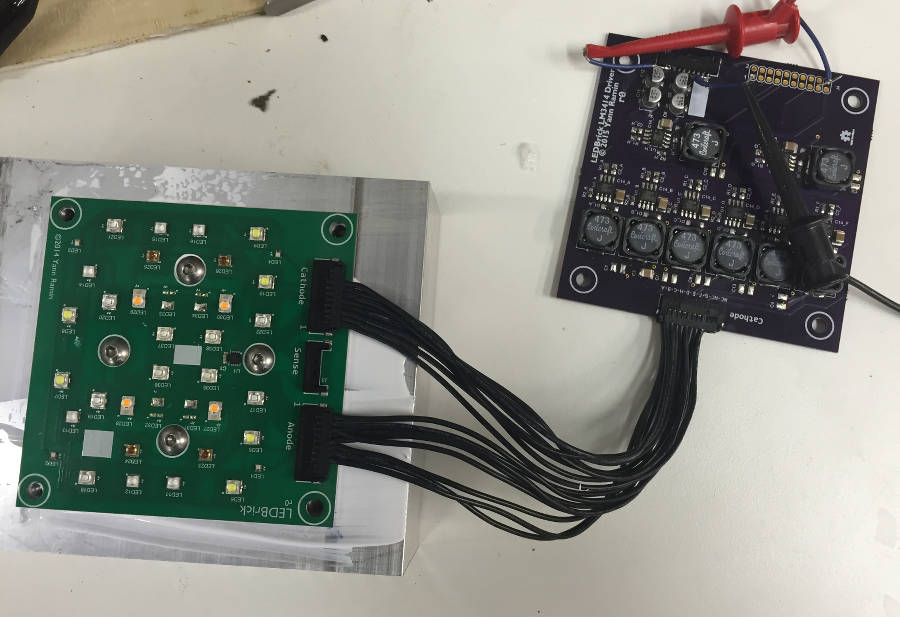 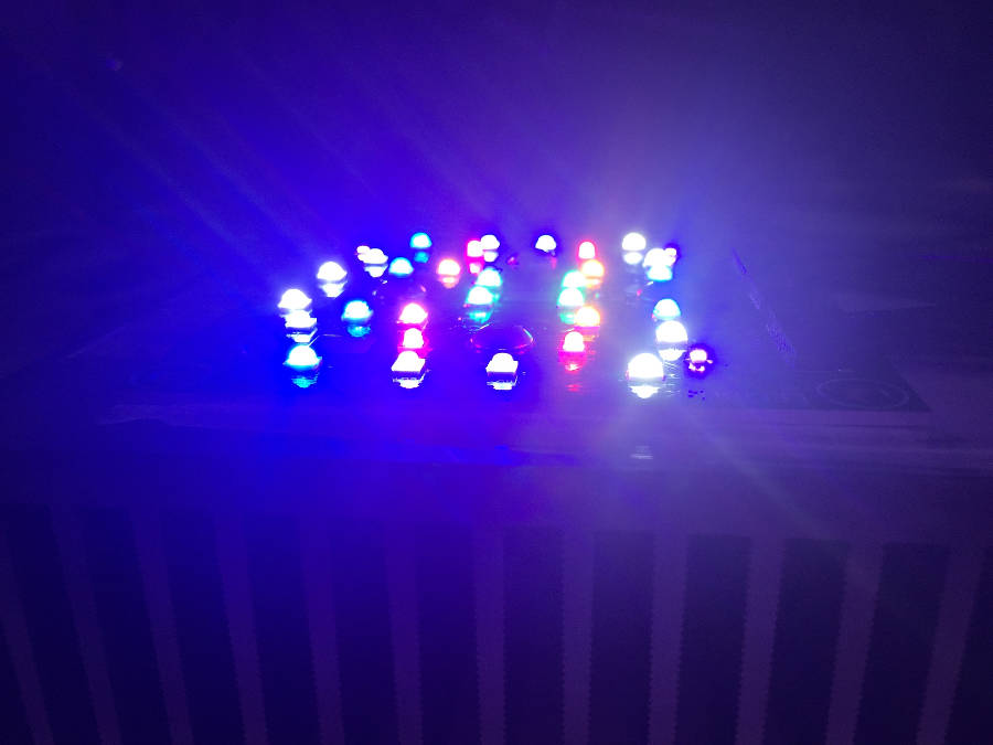 Minimum input voltage to the driver is about 18V. Set to 20V for testing. The LM3414 driver board is still cool, but I haven't evaluated long term with all channels running. 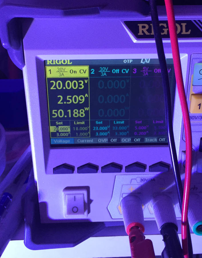
__________________
Custom electronics purveyor. blueAcro.com Current Tank Info: 90g SPS+mixed reef (10 yrs): LEDBrick LEDs, 40g custom sump, Ca reactor, chiller, Vortech, lots of custom electronics |
|
|
|
|
07/20/2015, 11:56 AM
|
#86 |
|
Registered Member
Join Date: Feb 2013
Posts: 204
|
Very nice! I've been waiting for a reveal. What is the footprint of the led board? Do you think the less could be grouped more tightly?
|
|
|
|
|
07/20/2015, 11:57 AM
|
#87 |
|
Registered Member
Join Date: Feb 2013
Posts: 204
|
Also when will you start selling ; )
|
|
|
|
|
07/21/2015, 11:23 PM
|
#88 | |
|
100-mile-commuter
Join Date: Dec 2004
Location: almost nevada
Posts: 4,721
|
Quote:
Yes, they could, with some thermal limits. The footprint of the board is identical to an 80mm fan. The heatsink is oversize a bit, and maybe a future rev would shrink those dimensions.
__________________
Custom electronics purveyor. blueAcro.com Current Tank Info: 90g SPS+mixed reef (10 yrs): LEDBrick LEDs, 40g custom sump, Ca reactor, chiller, Vortech, lots of custom electronics |
|
|
|
|
|
07/21/2015, 11:26 PM
|
#89 |
|
100-mile-commuter
Join Date: Dec 2004
Location: almost nevada
Posts: 4,721
|
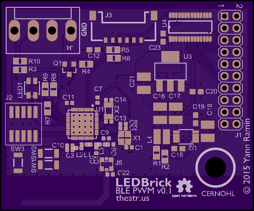
Update:
PWM board. Based on the nRF51822, which offers a Cortex-M0 and a Bluetooth LE 4.1 radio+stack. Its lacking in the hardware PWM land but, minus some radio interrupt glitches, is fast enough to bang out a reasonable software PWM. (The not yet released successor, the nRF52xx, will do full hardware PWM but thats EOY). Wire free, except for power!  Current WIP CAD board images: 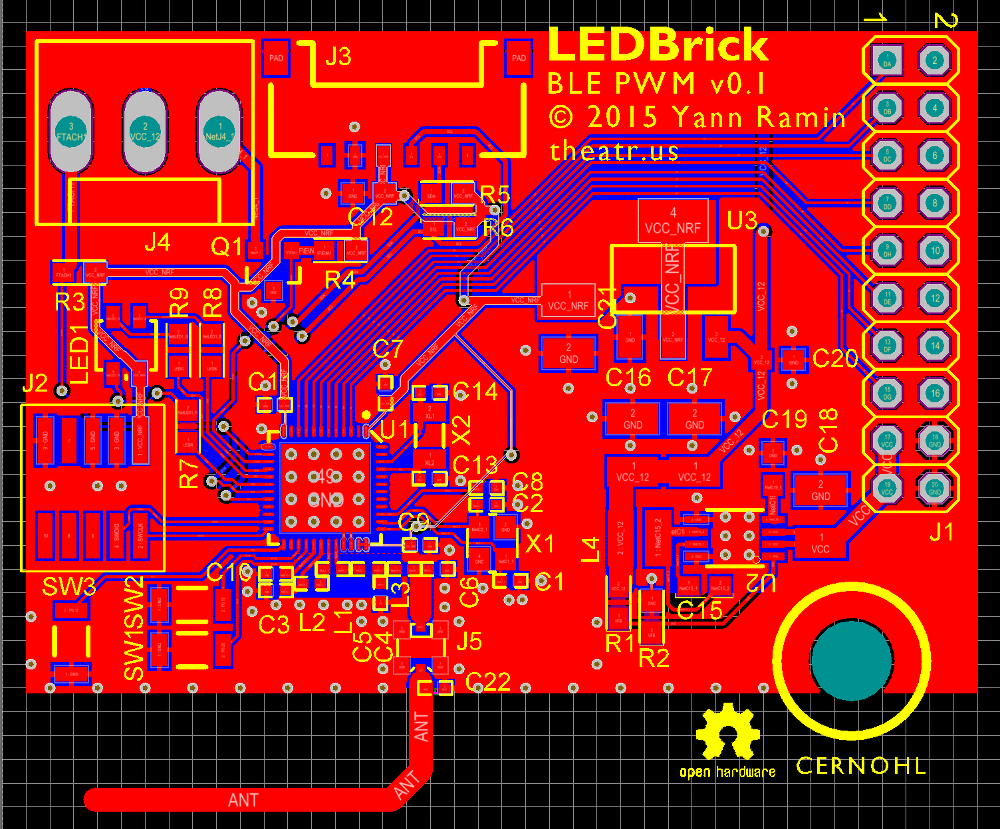 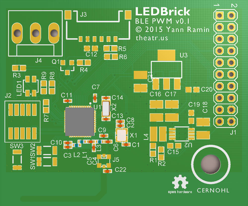 Messy schematics: http://theatr.us/images/ledbrick/pwm/schem.pdf As you can tell, this is about 1/6th the area of the driver, and could actually fit on the current footprint of the driver board for a future revision.
__________________
Custom electronics purveyor. blueAcro.com Current Tank Info: 90g SPS+mixed reef (10 yrs): LEDBrick LEDs, 40g custom sump, Ca reactor, chiller, Vortech, lots of custom electronics |
|
|
|
|
07/26/2015, 10:32 PM
|
#90 |
|
100-mile-commuter
Join Date: Dec 2004
Location: almost nevada
Posts: 4,721
|
For those asking about the efficiency of the LM3414HV driver, I did some in/out measurements today:
Test string: 6 (older) XP-G Cool White LEDs, warmed up. Cathode line has a 0.33ohm (0.33159 measured) resistor. Driver board has 4.7uF X7R ceramic output filter installed. Measured ripple at 304kHz is about 25mVRMS (there is a high frequency component ringing above 20MHz) Vin: 24.002V, 0.396A, 9.505W Vf: 18.105V, Istring: 0.498A, 9.0171W, 94.8% Vin: 19.004V, 0.488A, 9.274W Vf: 18.1299V, 0.4931A, 8.9398W, 96.5% Vin: 26V, ..., 94.7% Could be a bit higher, but as a whole it's good.
__________________
Custom electronics purveyor. blueAcro.com Current Tank Info: 90g SPS+mixed reef (10 yrs): LEDBrick LEDs, 40g custom sump, Ca reactor, chiller, Vortech, lots of custom electronics |
|
|
|
|
07/28/2015, 10:53 PM
|
#91 |
|
Registered Member
Join Date: Jun 2007
Location: los angeles
Posts: 303
|
tagging along
|
|
|
|
|
07/28/2015, 10:54 PM
|
#92 |
|
Registered Member
Join Date: Jun 2007
Location: los angeles
Posts: 303
|
very nice built.
|
|
|
|
|
08/01/2015, 11:25 PM
|
#93 |
|
100-mile-commuter
Join Date: Dec 2004
Location: almost nevada
Posts: 4,721
|
I played around with the mechanical bits while I wait for the PWM boards to arrive:
 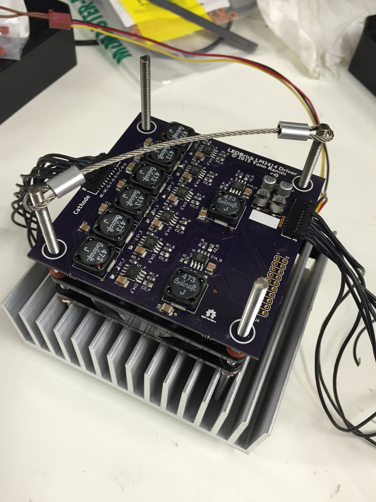 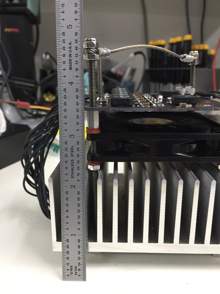 And it even hangs (mostly) balanced straight :-)
__________________
Custom electronics purveyor. blueAcro.com Current Tank Info: 90g SPS+mixed reef (10 yrs): LEDBrick LEDs, 40g custom sump, Ca reactor, chiller, Vortech, lots of custom electronics |
|
|
|
|
08/02/2015, 03:43 AM
|
#94 |
|
Registered Member
Join Date: Jan 2014
Location: Robin hood country, UK
Posts: 817
|
Really does look pretty smart
Tim |
|
|
|
|
08/02/2015, 11:07 PM
|
#95 |
|
100-mile-commuter
Join Date: Dec 2004
Location: almost nevada
Posts: 4,721
|
To make sure I'm in the right ballpark on light I tested a single LEDBrick (sans cyan channel, all channels at 500mA) against a set of 250W SE MH bulbs in a standard reflector, ARO Eballast. All are at 18inches, Apogee sensor is 6 inches off my garage floor. I did not correct for the -12% error from blue LEDs.
XM250 10k : PAR 147 1x LEDBrick 7 chan: PAR 112 Hamilton 14k: PAR 88 I'm planning one per 12", so that's 2 boards for every MH.
__________________
Custom electronics purveyor. blueAcro.com Current Tank Info: 90g SPS+mixed reef (10 yrs): LEDBrick LEDs, 40g custom sump, Ca reactor, chiller, Vortech, lots of custom electronics |
|
|
|
|
08/03/2015, 04:42 PM
|
#96 |
|
Registered Member
Join Date: Feb 2013
Posts: 204
|
Looks great! . This is Diy done right
|
|
|
|
|
08/09/2015, 06:41 PM
|
#97 |
|
100-mile-commuter
Join Date: Dec 2004
Location: almost nevada
Posts: 4,721
|
First cut of the PWM board is ordered.
 I made some small adjustments to it, including using a PCA9685 (whats another $2 to the BOM cost, and the PWM is jitter free) and supporting a 4 wire fan (there is also a FET to support a three wire fan with power control, if thats your kinda fun) I'll be updating the GitHub shortly, and the OSHPark board is here: https://oshpark.com/shared_projects/5Te0s49n
__________________
Custom electronics purveyor. blueAcro.com Current Tank Info: 90g SPS+mixed reef (10 yrs): LEDBrick LEDs, 40g custom sump, Ca reactor, chiller, Vortech, lots of custom electronics |
|
|
|
|
08/10/2015, 09:21 AM
|
#98 |
|
100-mile-commuter
Join Date: Dec 2004
Location: almost nevada
Posts: 4,721
|
The family is growing:
__________________
Custom electronics purveyor. blueAcro.com Current Tank Info: 90g SPS+mixed reef (10 yrs): LEDBrick LEDs, 40g custom sump, Ca reactor, chiller, Vortech, lots of custom electronics |
|
|
|
|
08/10/2015, 09:29 AM
|
#99 |
|
Registered Member
Join Date: Apr 2014
Location: Miami spring, Fl
Posts: 68
|
Looks awesome!
|
|
|
|
|
08/13/2015, 09:39 PM
|
#100 |
|
100-mile-commuter
Join Date: Dec 2004
Location: almost nevada
Posts: 4,721
|
Spent a lot of quality time crimping, and have four functional units, all sans Bluetooth PWM controller board.
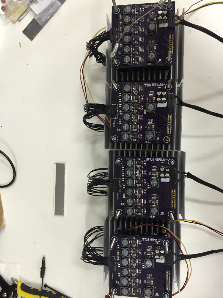 Here are two running, just because. 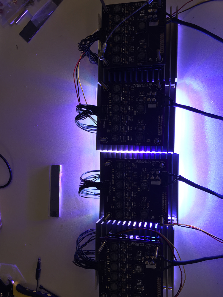 I'm experimenting with some shrouds on the splash guard. In this case, I applied some mylar tape to two vertical guards. This is all hand-snapped acrylic so excuse the imprecise edges: 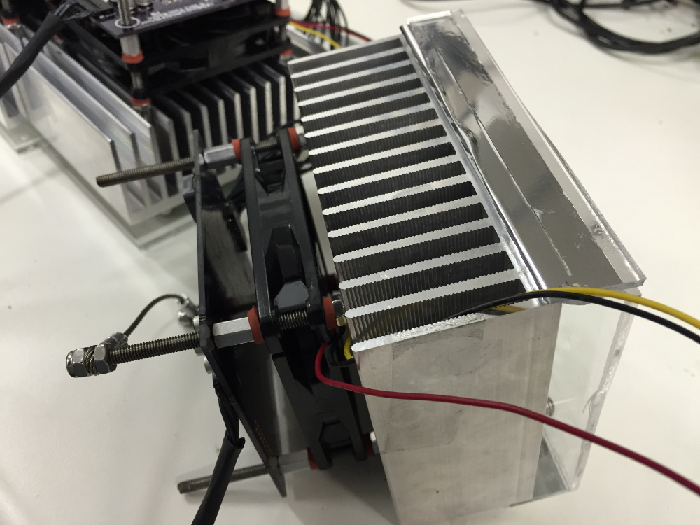 If nothing else, it helps cut down on accidentally looking straight at the diodes from the side 
__________________
Custom electronics purveyor. blueAcro.com Current Tank Info: 90g SPS+mixed reef (10 yrs): LEDBrick LEDs, 40g custom sump, Ca reactor, chiller, Vortech, lots of custom electronics |
|
|
|
 |
| Thread Tools | |
|
|


