
|
|
 07/23/2014, 10:33 PM
|
#7026 | |
|
Registered Member

Join Date: Jul 2014
Location: San Diego, CA
Posts: 27
|
Quote:
|
|

|

|
|
07/23/2014, 10:45 PM
|
#7027 | ||||
|
Registered Member
Join Date: Jul 2004
Location: AWOL
Posts: 12,013
|
Quote:
Quote:
Quote:
Quote:
 Oh, ignore the absurdity of the 2" gate valve on the intake: really pointless, [insert cheap ball valve here] but was the only 2" valve I had laying around at the time. 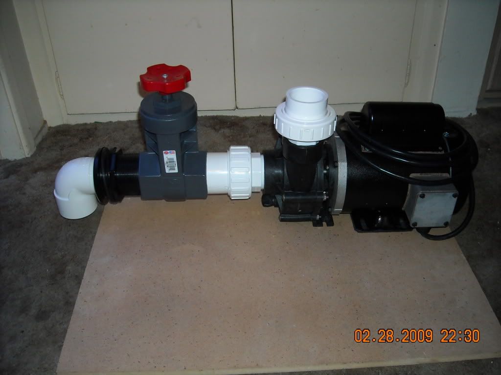
__________________
"Things should be made as simple as possible, but not simpler." (oft attributed to Einstein; most likely paraphrasing by Roger Sessions; compactly articulates the principle of Occam's Razor) Current Tank Info: 325 6' wide Reef |
||||
|
|
|
|
07/23/2014, 10:54 PM
|
#7028 |
|
Registered Member
Join Date: Jul 2014
Location: San Diego, CA
Posts: 27
|
looks like some sort of weapon. lol

|
|
|
|
|
07/26/2014, 06:08 PM
|
#7029 |
|
Registered Member
Join Date: Aug 2010
Posts: 838
|
Greetings. Haven't posted in a while but I just ordered a new DSA 65 Pro to replace the 60 gal tank I have now. We are moving so I used the move as an excuse for a new tank. WTH.
Anyway, this DSA tank has 3 holes in a center overflow box. I want to go with the Beananimal overflow but I'm not exactly sure just how to do it in a regular overflow box. I know the popular answer will be to go read the thread but I'm lazy and I'm not reading through 678,000,000,000,000 posts to find an answer!! 1) Are the elbows required or can you just use straight pipe? My 125 runs dual Herbie's but the pipes are straight, no elbows 2) How high up in the box can the full siphon be? The ones in my Herbie system sit about halfway up in the box but are choked back by gate valves so the water level sits well above them. 3) Shouldn't the open channel drain be above the full siphon? 4) At what level does the tubing sit at that comes out of the top of the open channel.
__________________
Current Tank: 125 gal mixed reef, 3-250 watt Radiums, T5 actinics, CS2 skimmer, RKL 60 gal "fun tank", 2-Ecotech Radions, Lifereef Overflow, build-in-progress |
|
|
|
|
07/26/2014, 06:59 PM
|
#7030 | |
|
Registered Member
Join Date: Jul 2004
Location: AWOL
Posts: 12,013
|
Quote:

__________________
"Things should be made as simple as possible, but not simpler." (oft attributed to Einstein; most likely paraphrasing by Roger Sessions; compactly articulates the principle of Occam's Razor) Current Tank Info: 325 6' wide Reef |
|
|
|
|
|
07/26/2014, 07:07 PM
|
#7031 | |
|
Registered Member
Join Date: Aug 2010
Posts: 838
|
Quote:
Thank you for pointing me in the right direction. That helps a bunch!
__________________
Current Tank: 125 gal mixed reef, 3-250 watt Radiums, T5 actinics, CS2 skimmer, RKL 60 gal "fun tank", 2-Ecotech Radions, Lifereef Overflow, build-in-progress |
|
|
|
|
|
07/26/2014, 07:50 PM
|
#7032 |
|
Registered Member
Join Date: Jul 2014
Location: San Diego, CA
Posts: 27
|
Gate valve showed up, thanks for pointing me in the right direction.
 took this pic just to show how big it is, man those fingers are like hotdogs. Lol Last edited by Misled; 11/02/2017 at 06:05 PM. |
|
|
|
|
07/27/2014, 10:01 AM
|
#7033 |
|
Registered Member
Join Date: Nov 2013
Posts: 45
|
So go with a schedule 80 gate valve....got it. The main plumbing is to be schedule 40. Now, can I assume that schedule 40 outside diameter is consistent with schedule 80 so that my PVC piping will have the right fit into a schedule 80 fitting or valve? Is the OD consistent, just the ID different due to a thicker sch80 wall? Thx.
|
|
|
|
|
07/27/2014, 10:15 AM
|
#7034 | |
|
Premium Member
 Join Date: Mar 2002
Location: Orange County, CA
Posts: 4,629
|
Quote:
(2) For aquariums, use a water level. 100% accurate, and cheaper too I'll bet you could make one with even going to the store
__________________
"You are a very fine person, Mr. Baggins, and I am very fond of you; but you are only quite a little fellow in a wide world after all!" - The Hobbit; J. R. R. Tolkien |
|
|
|
|
|
07/28/2014, 04:07 PM
|
#7035 | |
|
Registered Member
Join Date: Oct 2013
Location: Katy, TX
Posts: 422
|
Quote:
Please correct me if I am wrong... However, from research and what pump manufactures have told me in the past. Is it not best to put your flow regulating valve on the outlet side of a pump.... Have always been told regulating the inlet side can cause premature wear and tear... |
|
|
|
|
|
07/28/2014, 04:35 PM
|
#7036 |
|
Registered Member
Join Date: May 2005
Location: Perth, Western Australia
Posts: 8
|
Hi all. I have read quite a lot of this thread including at least the first 20 pages, but I can't seem to find the answer to my question. Is 5 mm clearance under the syphon elbow going to create problems? The overflow box is 95mm high and the weir lip is 1" below a rimless tank (36Lx18Wx24"H) with 1" plumbing throughout(no t pieces just elbows). The secondary is 12mm above the syphon and the emergency is about 10mm above the top of the down turned open drain. I will have the tube that comes out of the secondary sit about 10mm above the emergency and level with the lip of the weir.
Sound ok? |
|
|
|
|
07/28/2014, 04:49 PM
|
#7037 |
|
Registered Member
Join Date: Oct 2006
Location: ramsey illinois
Posts: 218
|
hello all
i am putting this type of overflow on 2- 40B`s i know it has been said in previous posts that it isnt needed on that size tanks but that is what i am going to do because this type of overflow looks to be the easiest to get built and adjusted if instructions are followed. the bulkheads i am using are 1 inch do i need to increase the drop pipe size to 1 1/2 inches or would 1 inch through out my build be sufficient. the tanks are going to be stacked on top of each other in a custom built stand the top tank will have a fall of approximately 54 inches the lower tank will only have about a 28 to 30 inch fall into the sump tank. the way they will be setup they will be straight down no elbows of any kind other than the elbows inside the overflow box and the elbow of the clean out Tee`s what do you think 1 inch all the way through or increase to 1 1/2 after the bulkheads? thanks for your suggestions James |
|
|
|
|
07/28/2014, 05:26 PM
|
#7038 | |
|
Registered Member
Join Date: Jul 2004
Location: AWOL
Posts: 12,013
|
Quote:
"Oh, ignore the absurdity of the 2" gate valve on the intake: really pointless, [insert cheap ball valve here] but was the only 2" valve I had laying around at the time." That said, there is nothing intrinsically wrong with a gate valve on the intake, other than it needs to be run full open, so it takes more than a 1/4 turn to shut off flow for pump removal. It is a mis-application of a gate valve, and it should be a ball valve; using a ball valve on the outlet is a mis-application of a ball valve. Ball valve: on/off. Gate valve: flow control.
__________________
"Things should be made as simple as possible, but not simpler." (oft attributed to Einstein; most likely paraphrasing by Roger Sessions; compactly articulates the principle of Occam's Razor) Current Tank Info: 325 6' wide Reef Last edited by uncleof6; 07/28/2014 at 05:42 PM. |
|
|
|
|
|
07/28/2014, 05:40 PM
|
#7039 | |
|
Registered Member
Join Date: Jul 2004
Location: AWOL
Posts: 12,013
|
Quote:
There really is no reason to be putting the bulkheads higher or lower in relation to each other, and no reason for the open channel to be above the siphon, or the siphon below the open channel (however one wishes to view it). The issue that this solves, is due to implementation errors, that can be avoided, by attention to detail, and an understanding of how the system works.
__________________
"Things should be made as simple as possible, but not simpler." (oft attributed to Einstein; most likely paraphrasing by Roger Sessions; compactly articulates the principle of Occam's Razor) Current Tank Info: 325 6' wide Reef Last edited by uncleof6; 07/28/2014 at 05:53 PM. |
|
|
|
|
|
07/28/2014, 05:49 PM
|
#7040 | |
|
Registered Member
Join Date: Jul 2004
Location: AWOL
Posts: 12,013
|
Quote:
The only problem you can expect, with 1" pipe, is that it does not get any worse than running a 1" durso, in terms of keeping them quiet, and bubble free. Well...a 3/4" durso would be worse... I would suggests 1.25" pipe on the 1" bulkhead for the open channel.
__________________
"Things should be made as simple as possible, but not simpler." (oft attributed to Einstein; most likely paraphrasing by Roger Sessions; compactly articulates the principle of Occam's Razor) Current Tank Info: 325 6' wide Reef |
|
|
|
|
|
07/28/2014, 05:57 PM
|
#7041 |
|
Registered Member
Join Date: May 2005
Location: Perth, Western Australia
Posts: 8
|
Please indulge me. My tank is only small so space is at a premium. Trying to get this box small as possible is important. Please explain if you would why this wouldn't work, and do the rest of the dimensions sound ok.
Many thanks. |
|
|
|
|
07/28/2014, 06:26 PM
|
#7042 |
|
Registered Member
Join Date: Jul 2004
Location: AWOL
Posts: 12,013
|
Friction losses, with water moving into the pipe, through a relatively small opening.
The dimensions you have provided don't tell me anything about the setup at all, other than relative positions. Read back several pages and look for the dimensions that are posted, as being critical, and we can go from there. Usually, when someone gets more concerned about making things as small as possible, rather than putting function first, they end up with a system that won't work as intended, because the critical dimensions are wrong.
__________________
"Things should be made as simple as possible, but not simpler." (oft attributed to Einstein; most likely paraphrasing by Roger Sessions; compactly articulates the principle of Occam's Razor) Current Tank Info: 325 6' wide Reef |
|
|
|
|
07/28/2014, 07:45 PM
|
#7043 | |
|
Registered Member
Join Date: May 2013
Posts: 127
|
Quote:

|
|
|
|
|
|
07/28/2014, 08:16 PM
|
#7044 | |
|
Registered Member
Join Date: Jul 2004
Location: AWOL
Posts: 12,013
|
Quote:
For external pumps, you do not want to increase the outlet pipe size larger than the intake pipe size. Doing so will cause the pump to cavitate. (pressure differentials.) But it is really easy to deal with this. Example: 3/4 inlet and outlet. We know that performance of the pump will increase, by increasing the outlet plumbing to 1". (Fluid Dynamics.) But this presents a dilema, a problem. The inlet/outlet size does not determine the size of the plumbing needed for a given pump in a given system. Flow rate and friction loss do. (keeping it simple, but variables such as distance to the intake volute from the source is also involved; lifting water e.g. pump higher than the water level in the source container as well, etc.) The way to solve the cavitation dilema, with our imaginary pump above, is to increase the intake plumbing size to 1". Larger outlet, larger inlet, a large as you care to go. With each pipe size increase, the actual output of the pump will increase, with the limitation of static head height on the flow curve, and an understanding that a plumbing system without friction loss does not exist. Submersible pumps are a different story. Since there is seldom, if ever, plumbing attached to the pump intake, the outlet pipe size rule does not apply, as the actual intake volute for the pump will always be flooded. Example: Mag Drive pumps 9.5 and larger require 1.5" outlet pipe to get any flow out of them. *********************************************************** I am certain that your 'overflow' design will get water out of the tank, but I think you need to work on it a bit more...without getting into the pertinent fluid dynamics, (things such as friction loss, single body of water vs hole in the side of an overflow) how you going to support that thing? I saw it a day or so ago, but the amount of typing would give me a headache... Look into such endeavors as bridging dual corner overflows, (a related topic) vs complete removal of corner overflows and replacing with much better designs....
__________________
"Things should be made as simple as possible, but not simpler." (oft attributed to Einstein; most likely paraphrasing by Roger Sessions; compactly articulates the principle of Occam's Razor) Current Tank Info: 325 6' wide Reef |
|
|
|
|
|
07/28/2014, 08:22 PM
|
#7045 |
|
Registered Member
Join Date: Oct 2006
Location: ramsey illinois
Posts: 218
|
thank you uncle for the suggestion i will use 1.25 inch for the plumbing then unless you see any benefit with me using 1.5 inch other than i have some laying around = cost savings is all?
|
|
|
|
|
07/28/2014, 08:42 PM
|
#7046 | |
|
Registered Member
Join Date: Oct 2013
Location: Katy, TX
Posts: 422
|
Quote:
I am no expert at all but the larger the outlet plumbing, the more dramatic the head pressure becomes... A pump would have to push up twice as much "water weight" with 1.5" plumbing than it would with 3/4" plumbing... You have twice the water weight, moving slower... |
|
|
|
|
|
07/28/2014, 10:39 PM
|
#7047 | |
|
Registered Member
Join Date: Jul 2004
Location: AWOL
Posts: 12,013
|
Quote:
With some things, it is far wiser to believe, than to not believe. However, when there is a natural science behind it, belief is not necessary. But yes, in a way you should not: 1.5" is the minimum size... I had never heard of such a thing, (such a large increase in pipe size being needed,) till it was put rather bluntly to me. I had always indicated it was prudent to increase the pipe size by one size. The mag drives are particuarly poorly engineered pumps...the flow increase is along the lines of several hundred gph.I direct you to the Danner Mag 9.5 instructions, page 2 just below the bar graph: http://www.dannermfg.com/Store/images/instructions/ZG100.pdf Pressure and weight are not the same thing. Weight involves mass and the acceleration due to gravity, it is static, at rest. Water is a liquid, pressure is static or dynamic (in motion,) and though it does have mass, and is affected by acceleration due to gravity, that has nothing to do with head pressure. Folks very often get weight and pressure mixed up. We have a 1" pipe, 100' tall. Filled all the way to the top with water. The pressure at the bottom of the pipe, (head pressure) is x. We move to the ocean, we go down 100', and we find that the pressure at that point is also x. Pressure at a given depth in a volumes of water, is equal, and it is equal in all directions, regardless of the size of the container, Not accounting for local ambient pressure. (Barometric pressure.) Though the weight of water in the ocean is far greater than the weight in our 1" pipe, at the same depth the pressure will be equal. So from this, it can be seen that weight is not a factor (e.g. how much does the water in the pipe weigh.) Having a pump push water up 100' in 1" pipe, the pump will see the exact same head pressure as it would in the middle of the ocean at the same depth. However, the output of the pump will be greater in the open ocean, than it will be in the 1" pipe. The reason is friction loss, or loss in pressure due to being in contact with the pipe walls, in the 1" pipe. There are several terms for pressure in fluid dynamics, but none of them are related to weight. Since this is dynamic, the natural science of this topic is called fluid dynamics, a subdiscipline of fluid mechanics, (deals with fluid flow) the natural science of liquids and gases in motion. More specifically it is Hydrodynamics...seperates it from Aerodynamics. We are getting pretty far away from the topic in this thread, however, fluid dynamics is important in drain systems, as well as return systems.
__________________
"Things should be made as simple as possible, but not simpler." (oft attributed to Einstein; most likely paraphrasing by Roger Sessions; compactly articulates the principle of Occam's Razor) Current Tank Info: 325 6' wide Reef Last edited by uncleof6; 07/28/2014 at 10:47 PM. |
|
|
|
|
|
07/29/2014, 10:55 AM
|
#7048 |
|
Registered Member
Join Date: Nov 2011
Location: Santa Rosa, CA
Posts: 2,727
|
Uncle speaks the truth. That's why a tall tank (other dimensions being the same) needs thicker glass/acrylic than a shallow tank.
__________________
John DT 120G. mixed reef w/ lots of automation + assorted FW and SW tanks. |
|
|
|
|
07/30/2014, 03:28 AM
|
#7049 | |
|
Registered Member
Join Date: Feb 2003
Location: Pittsburgh
Posts: 20,772
|
Quote:
The pressure at the bottom of a 10 foot tall drinking straw is the same as the pressure at the bottom of a 10 foot swimming pool is the same as the pressure measured 10 feet deep in the worlds largest ocean. |
|
|
|
|
|
07/30/2014, 03:39 AM
|
#7050 | |
|
Registered Member
Join Date: Feb 2003
Location: Pittsburgh
Posts: 20,772
|
Quote:
If the suction piping is properly sized, then the pump will NOT cavitate. regardless of the size of the discharge plumbing. It follows that if one restricts the suction side of the pump, then the discharge side must also be restricted to compensate for the lower pumping capacity, as otherwise the pump will cavitate. As for you split PVC overflow... many folks have fiddled with setups like that but they never work out well. Ignoring the fabrication and placement issues, the "slot" becomes easily overwhelmed by water. |
|
|
|
|
 |
| Tags |
| beananimal, plumbing |
|
|


