
|
|
 12/04/2009, 03:53 AM
|
#1 |
|
Registered Member
Join Date: Dec 2007
Location: Central California Coast.
Posts: 5,383
|
LED lighting on a budget!
Greetings fellow LEDites.
I know that LED lights are expensive to make and I want to show a way that might allow someone to proceed with less expense. This could allow new tank corals or allow one to reduce their electrical consumption, sometimes dramatically, from their existing HID or fluorescent setup. If this interests you read on. I'm going to explain a way to set up your LED lighting for bare bottom prices. How? We're going to forgo expensive drivers. How can we do this? With a little knowledge and some work. The only real limitation associated with this method is individual string dimming. This may or may not even matter to you. Why do this? Pros: 1) Substantially less expensive than using drivers. 2) Will generate less electrical noise if this is concern for you. 3) Simple! 4) Uses less space. 5) In some cases can be more efficient than using a driver. 6) Doesn't preclude one from changing over to drivers in the future when they hit the big jackpot. Cons: 1) Daily changes to the brightness of individual strings is not convenient enough to be viable. 2) In some cases this can be less efficient than drivers. 3) Takes a little more effort to setup. 4) No built-in current limiting protection as is typically found on drivers. (But we have a safe way around this.) Required tools are: a few hand tools, a voltmeter, and an ammeter. (This can be your typical DMM(Digital MultiMeter). You'll of course need anything else you require for building strings of LEDs. A calculator and some basic math ability may be useful. We can help you there. The data sheets for whatever LEDs you are using. If you haven't perused any of the various LED threads here you should probably do this before following this thread. OK a little background refresher on LEDs: LEDs are strange devices. They present a back voltage or blocking voltage against the power supply voltage you are supplying to them. This means that until you feed a LED with enough voltage to overcome this back voltage nothing much happens. Then once you reach the point where something does happen it can be way too much! Something is needed to 'ride herd' on the LEDs that will limit the current thru them to levels that are safe for them. This can be accomplished several ways. One is with a driver. Here, we are going to be using a power resistor. Let's put some numbers to this discussion. If we have a DC power source and a LED that we want to power we have to setup a circuit to correctly do this. Here's how: Let's look at a typical data sheet like the one for the Cree XR-E, (a popular choice), http://www.cree.com/products/pdf/XLamp7090XR-E.pdf Search around to find that 'back voltage' I refered to, it's called the FORWARD VOLTAGE, or the VOLTAGE FORWARD, or VOLTAGE F, or Vf In this case you will see it on page 4. FORWARD VOLTAGE @ 700mA. This is the voltage you will need to supply to this device to get it lit up properly at a current of 700mA or 0.7 Amps. What is the FORWARD VOLTAGE for the Cree XR-E? It's 3.5 Volts. This tells us that we need a power supply that can supply at least 3.5V to overcome the LED's resistance to passing 700mA. In this example lets say we have a 5V power supply. (This is a very common supply.) Now if we just hooked up our LED to this supply it would fry in about 2 seconds - never to provide a glimmer of light again. We need something to get rid of or soak up some of this excess voltage. What excess voltage? Starting with the 5V our supply will provide we then subtract the voltage the LED will carve off, 3.5V. 5V - 3.5V = 1.5V This leaves an excess of 1.5V that we will use a resistor to eliminate. What value of resistance? We turn to Ohms Law. 1.5V / 0.7A = 2.14 ohms. If we put a 2.14ohm resistor in our string of one LED and a 5V supply the LED will have 3.5V across it just as it needs. There is one other thing we must not forget. That's the power rating of the resistor. It tosses away power to drop that needed 1.5 Volts. We need to make sure it is physically big enough to handle the needed power. We calculate the power that will be dissipated. 1.5V X 0.7A = 1.05W or 1 watt. Now the rule for sizing resistors is to always double its power rating. This means we want at least a 2W resistor. This keeps the resistor cooler. It could still be too hot to touch but that's OK. Here's a picture to show what we have: 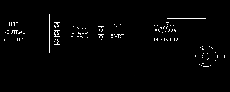 That's almost all there is to it. What's missing? Ummm Let's leave that for a little later as it will make more sense then. ############################### Alright, now we'll tackle a more typical set up for lighting a tank. Instead of a power supply, a resistor, and a single LED, we will use a bunch of LEDs. But how many can we use? It depends on the power supply's voltage. If you look around you will find that 24VDC is a fairly common size that can be had for very little money. We'll work with that but most any voltage will do the trick. If we have a 24V supply how many of those CREE XR-E LEDs should we hook up as a chain in series? Take the supply voltage and divide it by the FORWARD VOLTAGE. 24V / 3.5V = 6.86 We could hook 6.86 LEDs up in a row and the 24VDC supply would just barely run them. Except we of course can't buy or make 0.86 of a LED. So we round down to 6. We can hook up 6 LEDs in series to the supply with our resistor in series with the chain. We should hook these up with typical electronics protocol of -> Power supply (+) output to the resistor. From there we go to the (+) on the first LED then from this first LED's (-) to the next LED's (+) continuing on to the last or sixth LED's (-). This last (-) gets hooked back up to the power supply's negative or (-) terminal completing this LED "chain" or "string". That's the basic layout. But we need to figure out what resistor to use. Back to the math. Just like our first single LED calculation we do the same here. 24V - 3.5V - 3.5V - 3.5V - 3.5V - 3.5V - 3.5V = 3V From this we see we need to carve off 3V of excessive voltage. If we want to run the sting at 700mA or 0.7A we proceed as follows, 3V / 0.7A = 4.29 ohms. We need a 4.29 ohm resistor. What power rating? Again: 3V x 0.7A = 2.1W. Double this and we need at least a 4.2Watt 4.29ohm resistor. No they don't sell these at Safeway! Fret not though. Here's what you use. http://www.heiresistors.com/PDF/AVT_AST%20Spec.pdf Note these are 25W resistors! So they have us easily covered in power capability. They cost about $5 apiece from Digikey. You can probably find them elsewhere for less than that. That is an adjustable resistor. You can set it to 4.3ohms. What we do is use a multimeter to set it as close as you can to 4.3ohms. You can measure this in-circuit with no difficulty. So install everything then adjust the resistors. If your multimeter has a 1A or larger current measuring ability you can break the circuit somewhere and directly measure the current. Alternatively you can write down the actual resistance you set the resistor to and then with the string powered up and running directly measure the voltage across the resistor. Run back to Ohms Law and calculate the actual current. If your resistor was set to 4.3ohms and you measure 3.2V you have this: 3.2V / 4.3ohms = 0.744A Shut down and re-adjust the resistor to make it "longer" which will raise its resistance driving down the current a bit. That's almost all there is to it. Hmmm what are we forgetting? Protection! We need a fuse in each string. It should be between the power supply and the resistor. For a 700mA string you will want a 1A fast blow. This will prevent a fire should something go wrong. What could go wrong? A wire from one of your solder joints could come loose. Or an LED could decide it's done and short. If any one LED shorts it will increase the current of the entire string. How much? That resistor that's there to set the current at 700ma in the above example by having 3V across it, would then have about 3V + 3.5V equaling 6.5V. Running back to Mr. Ohm this would result in 6.5V / 4.3ohms = 1.15A which would blow our 1A fuse protecting the rest of the LEDs. You can use one of these Digikey F2313-ND. http://search.digikey.com/scripts/Dk...3-ND&x=14&y=14 These are not the conventional glass fuses you're probably familiar with. These are much less costly and need no holder. Of course you can buy holders and use the typical glass fuses if you prefer. So lets do a walk thru of a full hood. 1) Find your heat sink. 2) Figure out your LEDs. 3) Check the Forward Voltage of your selection. Example: 3.5V 4) Decide on the drive current. Example 700mA same as 0.7A 5) Figure out how many you want to run on your fixture. Example: 60 6) Hunt down a power supply by assuming a common output voltage. Example 24V 7) Calculate the size the strings must be: 24V / 3.5V = 6.8 -> round down to next whole number -> 6 8) Calculate how many strings. 60LEDs / 6LEDs per string = 10 strings. 9) Calculate expected resistor value. 24V - 3.5 - 3.5 - 3.5 - 3.5 - 3.5 - 3.5 = 3V 3V / 0.7A = 4.3ohms 10) Calculate the minimum power rating of this resistor. 3V x 0.7A = 2.1W Double this -> 4.2W Any wattage greater than this will work. You can use the one above: http://search.digikey.com/scripts/Dk...me=AVT25-10-ND 11) Get the mounts for the resistors to make the mounting of them much easier. (2 per resistor) http://search.digikey.com/scripts/Dk...&name=B1003-ND 12) Purchase 1A fuses in this case (10). http://search.digikey.com/scripts/Dk...&name=F2313-ND 13) Figure out your LED positions and cut the appropriate length pre-tinned stranded 20AWG to interconnect them. 14) Solder them together with the correct polarity. Then mount them to the heatsink. 15) Mount the resistors. 16) Pickup three terminal blocks like these: http://search.digikey.com/scripts/Dk...name=A98521-ND 17) Mount the two terminal blocks separated the exact distance needed to have those fuses clamped under the screws spanning two of these terminal blocks. This allows you change a fuse or to conveniently disconnect an individual string or disconnect one side and insert an ammeter to measure the current. Don't install the fuses yet! 18) Use the screw adjacent to the fuse to connect to one side of your power resistor. 19) The other side of the resistor goes to the proper polarity side of the first LED in this string. 20) Jumper all the screws on the other side of the fuses together. This will be your +24V bus from your power supply. 30) Mount your third terminal block nearby. Jumper all of one side together. This will be your 24V RETURN bus. 31) Connect the far end,(last LED), of all your strings to the remaining screws on the 24V RETURN bus. 32) Using your ohm meter and a screw driver set all your resistors to a little higher than the number we arrived at above. This is to protect from variation in your LEDs as the 3.5V number is only an average and not definite. So set the resistors around 5 ohms. 33) Back to the power supply!! This one pointed out by SpacedCowboy can't be beat for value. http://www.mpja.com/prodinfo.asp?number=16855+PS We plan to have 10 strings and each draws 0.7A so how many amps total will a supply have to provide? 10 x 0.7A = 7A. The aforementioned supply provides up to 8.3A! So it should supply 7A just fine. I would never try to get the full rating from a supply as that is bad engineering and will reduce operating margins and system lifetime. 34) Mount the supply somewhere that is not going to EVER get wet, is out of reach of rug rats, and allows plenty of free air flow. Make sure the terminal strip on the supply can't be touched accidentally as it will have 120VAC somewhere on it. You will probably want to include a power switch somewhere. 35) Using two stranded pre-tinned 16AWG wires of the required length connect the supplies 24V RETURN to the previously prepared Ground Bus. Run these wires onto two screws that divide the bussed together side of the barrier block into thirds. This will balance the current in the bus jumpers you installed. You would not want the current to have to work its way all the way down the jumpers to the far end of the strip. You also want the wires from the supply to be big enough to handle the current if one wire is disconnected. Hence the 16AWG. 36) With too more wires connect the +24V to the bussed side of the fuse strip we've already prepared in a similar manner. 37) Review your work! 38) Power up. 39) Measure the output voltage. Is should be close to 24V. If it is power it down. 40) Measure the first string's resistor and write down the number. 41) Hook up this string's fuse. Switch your meter to Volts. Power up again. If you did everything correctly the string should light up! It will be shockingly bright. Promptly measure the voltage across the resistor. Write this down. And immediately turn off the power. 42) Divide the voltage you just measured by the resistance you previously measured. The result is the current you have running thru your string. Is it 0.7A or less? If it's not where you want it adjust it. Re-measure the resistance - power up - measure the voltage and power down. Do the math again. Repeat this until you're satisfied. 43) Now this string will give you a visual reference to compare the rest to. Go ahead, and while cycling the power, hook up more strings by installing their fuses. Power up looking for any strings that seem brighter. Check their current and adjust it if required. 45) Once they are all up and running you're there! Here's what it looks like: 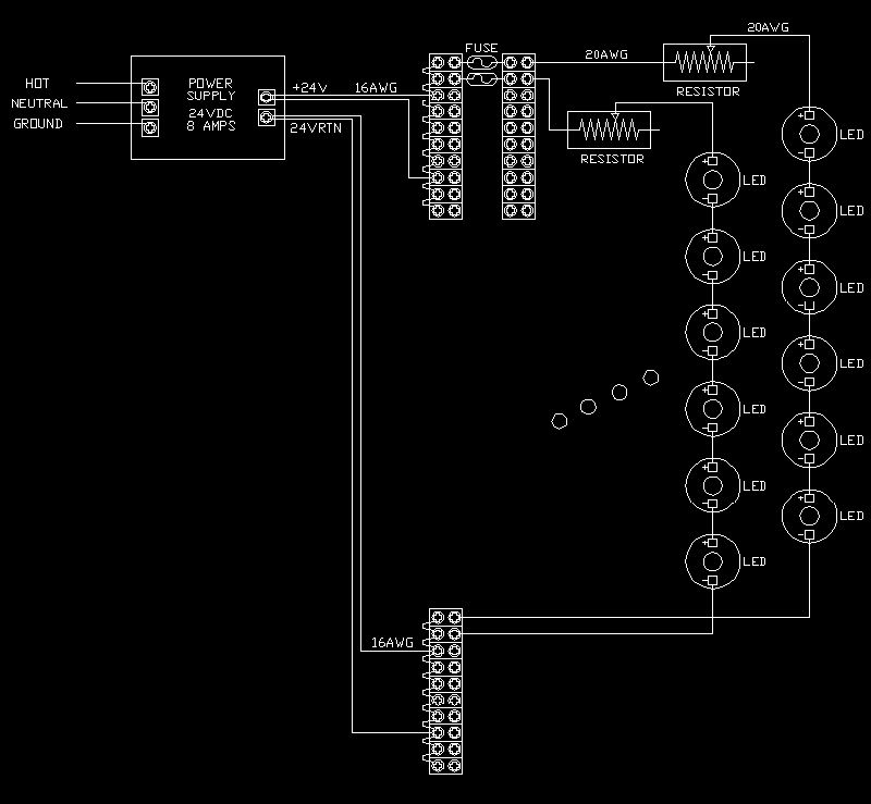 Some things to remember: A) As you fire up more strings the system voltage will drop a little so don't go crazy trying to adjust the string currents to some crazy accuracy it's just not necessary. B) Most power supplies have a Trim Voltage Adjust Screw. You can change the entire fixture's overall brightness by whatever that trim adjust allows. So, once the whole thing is running you could turn the whole fixture down a little to allow for some acclimation. If it doesn't dim enough you can, of course, adjust any or all strings individually to whatever you want. C) If you want large adjust-ability of the entire fixture you could actually use a lab power supply that allows you to turn a knob to adjust the voltage of the entire fixture over a large range. This would probably be overkill unless you have some special need. D) But what about efficiency, isn't this setup likely to be very inefficient? We are looking at 190W to provide 147W of LED light. 147W/190W => 77% BuckPucks land around 79% with this same design. Mean Well efficiency is about 82% If you want to get crazy about efficiency you adjust your supply voltage so that you need even less voltage across our power resistors. If you do this correctly you can beat the Mean Wells by a few percent, but I don't think it's required and it will reduce your system flexibility a little. Since this build is supposed to reduce cost over active current regulation what does the cost shake out as? Here's a single channel's expense: $0.62 Fuse $5.92 Resistor $1.00 Resistor mounts $0.66 One string's fraction of terminal blocks($6.60) $2.00 One string's fraction of the power supply(20.00) ------------------------------------------------------------------ $10.20 To drive one string. (In this case 6 HBLEDs) The MeanWell 60-48 costs about $50 and can run 13 LEDs. Or $23 for 6 LEDs. The MeanWell solution costs more than twice our resistor regulation method. It does allow dimming, (with added equipment). This means our entire 60LED example would cost about $100 + 60LEDs. The equivalent MeanWell solution would ring up to about 5 x $50 = $250 + LEDs. This setup also allows a very easy change to drivers if that becomes necessary or desirable. |

|

|
|
12/04/2009, 06:31 AM
|
#2 |
|
Registered Member
Join Date: Jul 2008
Location: frederick, maryland
Posts: 96
|
Nice write up, simple and easy to follow

|
|
|
|
|
12/04/2009, 07:27 AM
|
#3 |
|
Registered Member
Join Date: Jul 2003
Location: N. Florida
Posts: 129
|
Your drawings and parts sourcing make this project appear very doable. Would the terminal strips, fuses, and resistor portion be best mounted in a project box?
__________________
Click the red house to visit my LED build thread......... Phil Current Tank Info: 55 gal mixed reef w/100 gal rubbermaid sump W/ Vertex Alpha skimmer |
|
|
|
|
12/04/2009, 08:18 AM
|
#4 |
|
Registered Member
Join Date: Feb 2006
Location: Michigan
Posts: 86
|
How many LED's are needed per gallon? Is there a general rule?
|
|
|
|
|
12/04/2009, 09:41 AM
|
#5 |
|
Registered Member
Join Date: Apr 2008
Location: Grove City, Ohio
Posts: 10,806
|
WOW! I would like to hear some comments for some other DIY electrical guys! Very well written - if this is for real I may have just found my next project!
Thanks very much
__________________
I'll try to be nice if you try to be smarter! I can't help that I grow older, but you can't make me grow up! Current Tank Info: 120 mixed reef with 40b sump, RO 150 skimmer, AI Sol Blue x 2, and a 60g Frag Tank with 100g rubbermaid sump. 2 x Kessil A360w lights, BM curve 5 skimmer |
|
|
|
|
12/04/2009, 09:50 AM
|
#6 |
|
Team RC Member
Join Date: Sep 2003
Location: NY
Posts: 17,749
|
This is fantastic.
chvojka, I'd suggest you check out some of the other LED threads in here, the "basic" questions are very well covered.  kcress, can we do a cliff's notes of advantages and disadvantages of this approach over regular drivers? I'm not sure I'm picking it up correctly. Advantages: 1) Cheaper than commercial products 2) Less electrical noise 3) You have full control, since you built it Disadvantages: 1) No dimming or controllability (could it be added without getting too complex?) 2) Is there potential for inaccuracy if the resistor or power supply drift? I need to do a thread on my DIY drivers. It's interesting that the cost ends up being almost exactly the same as this solution - but you get controllability, at the tradeoff of a far more complex circuit.
__________________
Inconveniencing marine life since 1992 "It is my personal belief that reef aquaria should be thriving communities of biodiversity, representative of their wild counterparts, and not merely collections of pretty specimens growing on tidy clean rock shelves covered in purple coralline algae." (Eric Borneman) |
|
|
|
|
12/04/2009, 10:06 AM
|
#7 |
|
SPSahollic
Join Date: Jun 2008
Location: terneuzen , netherlands
Posts: 875
|
cool write up

__________________
May the flow be with you ! Current Tank Info: 154 G SPS dominated + 25 G sump ; lighting : 210 W LED XPG/XRE (sunrise) + 150 W T5 (bl+ , 15°K , fiji , bl+) ; skimmer : Royal Exclusive supermarine 200 ; BM 3-Ch dosing pump (CA/ ALk and top-off) ; tunze 6085 circulation |
|
|
|
|
12/04/2009, 10:13 AM
|
#8 |
|
Moved On
Join Date: Oct 2008
Location: here.
Posts: 2,509
|
Funny this thread just popped up....I just had a rep come by my shop with these new leds from jt out of china...there pretty cool and all self contained no need for soldering or making anything...very simple plug and play...there only 1w leds but very bright and cheap they run 9dollars a foot bassically boils down to 3dollars a led since there is 4 per foot....not sure what kind of par we could get since I don't have a meter but honestly by the looks of them if you doubled up what most people are using I don't see it being a problem....pics to come shortly....not trying to highjack or anything just thought your tittle was perfect these are cheap and anyone can diy with these.....
|
|
|
|
|
12/04/2009, 10:28 AM
|
#9 |
|
Moved On
Join Date: Oct 2008
Location: here.
Posts: 2,509
|
here is a couple shots of them...built in heat sinks and all....
lmk. what ya think.... 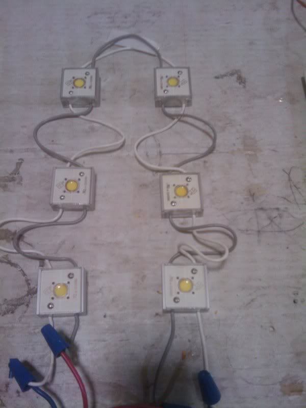 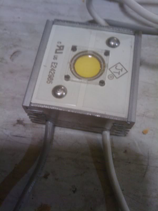 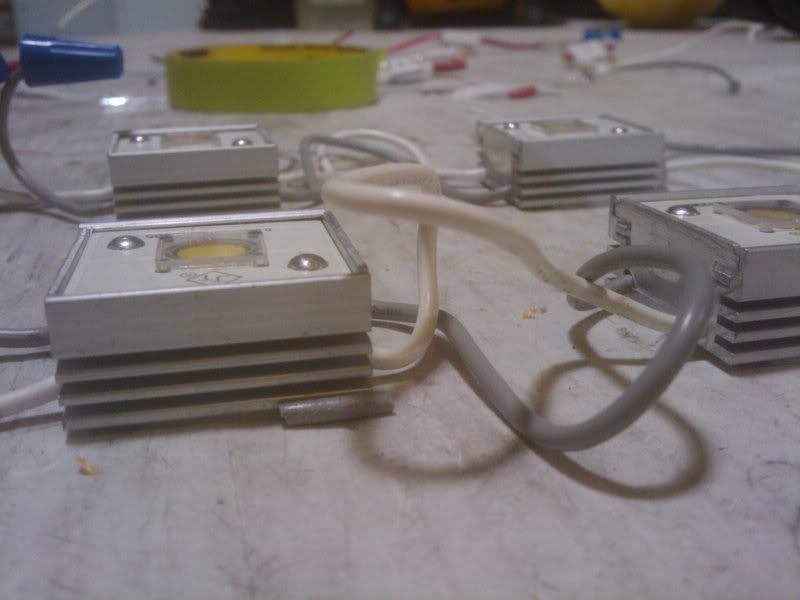 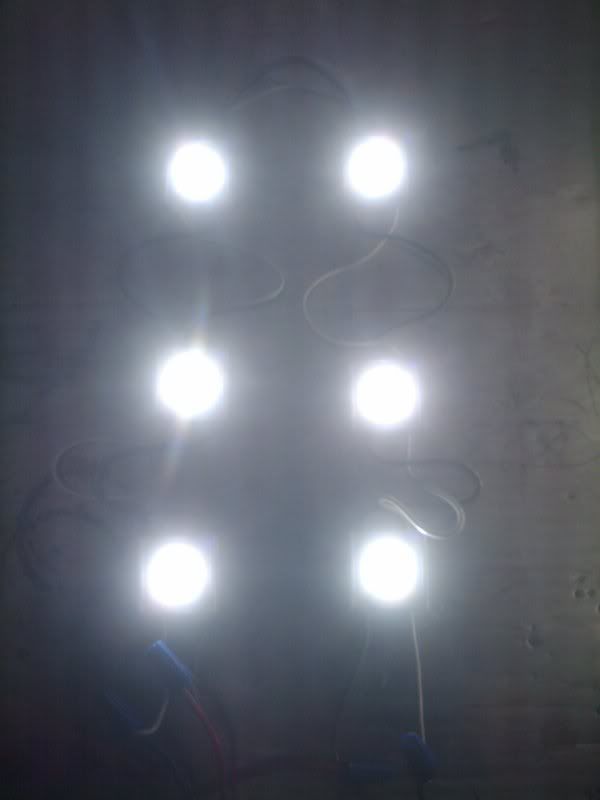
|
|
|
|
|
12/04/2009, 10:30 AM
|
#10 | |
|
Team RC Member
Join Date: Sep 2003
Location: NY
Posts: 17,749
|
Quote:
If you have Q5 XR-E running at 350mA, they are 107 lumens/watt. If we assume your mystery LEDs are half as good (fair assumption, since that puts them in range with many "average" HB LEDs) at 50 lumens/watt, then you'd need twice as many to provide the same light. This doesn't seem like a big deal up front when you're buying the LEDs, since the mystery LEDs will likely be cheaper. But longterm, you lose out BIGTIME. The mystery LEDs will cost twice as much money (watts) to produce the same light, so your power bill will be double! Given that, you'd almost certainly be better off using known-efficient LEDs rather than mystery LEDs for primary illumination. Even if the mystery LEDs were totally free, the known-good LEDs would pay for themselves after a year or two. Hence, when trying to cut costs on a LED project, the one place you NEVER want to skimp is the LEDs themselves. Financially, it makes much more sense to find cost trimmings by projects like this (DIY'ing drivers).
__________________
Inconveniencing marine life since 1992 "It is my personal belief that reef aquaria should be thriving communities of biodiversity, representative of their wild counterparts, and not merely collections of pretty specimens growing on tidy clean rock shelves covered in purple coralline algae." (Eric Borneman) |
|
|
|
|
|
12/04/2009, 10:32 AM
|
#11 |
|
Moved On
Join Date: Oct 2008
Location: here.
Posts: 2,509
|
you know better than me willie....thats why i asked.....lol
im a plastics guy but when i saw these this morning you guys were the first people who crossed my mind....no biggie..
|
|
|
|
|
12/04/2009, 10:34 AM
|
#12 |
|
Moved On
Join Date: Oct 2008
Location: here.
Posts: 2,509
|
here is a little info i found on them..sorry 1.5watt..
1.5W High Power Module-White Operating Voltage Rated Current Rated Power Dimension Viewing Angle Wavelength Luminous Intensity LED Amount Waterproof Feature 12V DC 120mA 1.5W 28×28×12mm 120° — 65-70 lm 1 IP65 |
|
|
|
|
12/04/2009, 10:43 AM
|
#13 |
|
Team RC Member
Join Date: Sep 2003
Location: NY
Posts: 17,749
|
It's an interesting prospect and worth discussion. For someone experimenting on a nano something like that might be fun to play with - I should note that my razor sharp focus on efficiency and longterm cost is coming from the perspective of designing an LED rig for my 360g tank that I want to be cost effective over at least a 10 year life, so my criteria might be different than others.
__________________
Inconveniencing marine life since 1992 "It is my personal belief that reef aquaria should be thriving communities of biodiversity, representative of their wild counterparts, and not merely collections of pretty specimens growing on tidy clean rock shelves covered in purple coralline algae." (Eric Borneman) |
|
|
|
|
12/04/2009, 10:46 AM
|
#14 | |
|
Registered Member
 Join Date: Aug 2008
Location: US ARMY - El Paso TX
Posts: 3,678
|
to make it easier on myself to find several threads of interest, i have made a folder of various RC build threads & DIY links & this one was just added to my LEDs folder
 not only does your explanation broken down in steps make it easy to understand, it should be easy to modify the thought process to fit an individual's needs for their perticular setup & the visualizations make it easy to understand as well....EXCELLENT (/bill & ted) LOL my next build i will be on the smaller side, so i'll have to do a pre-build pricing breakdown to see if the savings will be substanial enough versus just buckpucks Quote:
LOL
__________________
Yes I hear voices in my head, but they speak spanish so I can't understand anything they say. there's no place like 127.0.0.1 It's a shame that stupidity isn't painful.... Current Tank Info: currently tankless....but planning an AIO |
|
|
|
|
|
12/04/2009, 01:06 PM
|
#15 |
|
Premium Member
Join Date: May 2004
Location: Longmont, Co
Posts: 4,566
|
Remember when LONG ago Someone said that you didnt NEED a CC driver
  I have also built my own with just a LM317 adjustable regulator, 2 caps, a resistor, & old cellphone charger for my QT tank. Stu
__________________
Some people think that I have Attention Deficit Disorder. They just dont understand that........ Hey! Look a chicken! Well, We KNOW GOD exists, but for US to exist without a GOD is preposterous .Umm wait a minute . Sounds a bit circular to me Current Tank Info: 125 Gal. display w/80 gal mud/caulerpa sump. Basement sump w/ LED Grow Light,Gravity fed Reeflo200 skimmer w/ ORCA Recirc, DIY calc reactor & kalk stirrer. Inline plumbed 75 Gal frag/settling tank. |
|
|
|
|
12/04/2009, 01:13 PM
|
#16 | |
|
Team RC Member
Join Date: Sep 2003
Location: NY
Posts: 17,749
|
Quote:
__________________
Inconveniencing marine life since 1992 "It is my personal belief that reef aquaria should be thriving communities of biodiversity, representative of their wild counterparts, and not merely collections of pretty specimens growing on tidy clean rock shelves covered in purple coralline algae." (Eric Borneman) |
|
|
|
|
|
12/04/2009, 05:12 PM
|
#17 |
|
Registered Member
Join Date: Jul 2007
Location: lawn guy land
Posts: 1,418
|
thanks kcress for the informative post
|
|
|
|
|
12/04/2009, 07:20 PM
|
#18 |
|
Premium Member
Join Date: May 2004
Location: Longmont, Co
Posts: 4,566
|
kcress,
Nice find on the resistors! I was using some of those AVT-200s just the other day intentionally burning some stuff up in the lab. Very nice write up! Extreme detail ( We should get paid for this stuff  ) )Stu
__________________
Some people think that I have Attention Deficit Disorder. They just dont understand that........ Hey! Look a chicken! Well, We KNOW GOD exists, but for US to exist without a GOD is preposterous .Umm wait a minute . Sounds a bit circular to me Current Tank Info: 125 Gal. display w/80 gal mud/caulerpa sump. Basement sump w/ LED Grow Light,Gravity fed Reeflo200 skimmer w/ ORCA Recirc, DIY calc reactor & kalk stirrer. Inline plumbed 75 Gal frag/settling tank. |
|
|
|
|
12/04/2009, 07:45 PM
|
#19 |
|
Super Premier Member
Join Date: Jul 2007
Location: Norristown, PA
Posts: 849
|
WOW!!!
Yes it was worth the wait. 60LEDs and only 100 in parts, yeah baby. |
|
|
|
|
12/04/2009, 08:50 PM
|
#20 |
|
One reef to rule them all
Join Date: Sep 2009
Location: Leominster, MA
Posts: 5,299
|
So since I am no electrician and simply have to take people's word for it when they explain a DIY like this, do we have any pics of ones of these babies in action for those like me who like visual gratification? :LD
__________________
"A dog is the only thing on earth that loves you more than you love yourself" ~ Josh Billings Visit My Home page for current build thread (click my user name and select "Visit LordoftheReef's Homepage" in the drop down menu! |
|
|
|
|
12/05/2009, 01:11 AM
|
#21 |
|
Drug Enthusiast
Join Date: Oct 2007
Location: Rochester, MN
Posts: 2,958
|
That's quality Kcress. Now all we need is for the LED's themselves to drop by half in price :-)
|
|
|
|
|
12/05/2009, 04:35 AM
|
#22 | |||||||||||
|
Registered Member
Join Date: Dec 2007
Location: Central California Coast.
Posts: 5,383
|
Quote:
Quote:
Quote:
Quote:
Thanks der_wille_zur_macht and for your great support to all the posters here. Your Dimming point. Yes you can dim with this system but you have to do it by dimming the entire system with a voltage change at the supply. Well you could actually do it with some Frankenstein giant rheostats or something but eeeeeuw. As to your drift question. Certainly, but I would expect only a few percent. Noting you could see and possibly similar to current drivers themselves. Quote:
Quote:
Quote:
Quote:
Thanks stu. Yeah these things take a heck of a lot of time to write! As I do them I marvel at people who write frikken books! Yikes!Yes I started out looking at small power rheostats thinking they would be most easy to adjust but in multiwatt varieties they cost as much as drivers!!! Then I found these and started to realize they were higher power, smaller, and more robust. Quote:
 Quote:
 Quote:
|
|||||||||||
|
|
|
|
12/07/2009, 04:48 PM
|
#23 | |
|
Registered Member

Join Date: Mar 2006
Location: Cincinnati, OH
Posts: 131
|
Quote:
|
|
|
|
|
|
12/07/2009, 06:55 PM
|
#24 |
|
Registered Member
Join Date: May 2006
Posts: 1,135
|
IIRC, you are using the symbol for a variable resistor after the power block/fuse.
For dimming capability, couldn't you just add the fixed resistor where you show the variable and add a variable before the fuse? This should allow for dimming of each string. Please correct me if I am wrong, it has been awhile since I took an electronics class. |
|
|
|
|
12/07/2009, 06:57 PM
|
#25 |
|
Registered Member
Join Date: May 2006
Posts: 1,135
|
Oops, sorry. The symbol is for a potentiometer not a variable resistor.
|
|
|
|
 |
|
|


