
|
|
 11/26/2003, 04:27 PM
|
#1 |
|
Premium Member
 Join Date: May 2003
Location: California
Posts: 2,022
|
Anti-RO/DI Cycling ATO Reservoir Device
Maybe I should try and think of a shorter name.
 I posted some information and images to a project I have been working on at my thread but thought I would duplicate it here. It's better suited here anyways considering all the creative minds that frequent this forum. So here is the text and photos for your review and possible enjoyment; I posted some information and images to a project I have been working on at my thread but thought I would duplicate it here. It's better suited here anyways considering all the creative minds that frequent this forum. So here is the text and photos for your review and possible enjoyment;So I've been mentioning that I've been working on updating my auto top off (ATO) system. What I was trying to achieve or improve upon was to reduce the amount of times the RO/DI filter was cycling on and off. Currently, my system includes a small reservoir which is feed by the RO unit with a float valve to regulate the water level. This then feeds my Kalk-Reactor via gravity and then continues to another float valve located in my sump. This valve maintains a constant level for the tank and provides the Kalkwasser (calcium water) additions for the coral growth. The problem with this system is that the float valve in the reservoir is constantly cycling the Ro unit because it turns on with only a small decrease in water level; the evaporative tank water replenishment throughout the day. This wouldn't be an issue if it weren't for the fact that RO units apparently pass small amounts of impurities every time they start production. So, the more times it cycles, the more impurities get passed through and to the tank. This is not ideal or a good thing. The best or one way to decrease this amount of impurities is to have the RO cycle less by producing a large amount of water at a single time. I didn't want to give up on my overall ATO design due to the fact that it's worked flawlessly for many years, at least I thought prior to recently learning of the impurities issue. I knew I could increase the reservoir size which would help slightly but not to the level I needed. What I really needed was for the reservoir to empty almost to the very bottom before the RO unit would start and fill it to the top again. And, I needed to do this with a single, mechanical float valve. Hmmm. Better turn the left brain up a notch for this one. What I came up with is a fairly simple design that does in fact utilize only one float valve. Although I will be adding a second as a backup, safety device. A good way to see the design in action is to fill your sink with water and then submerge a drinking glass in it. Now, turn the glass up side down, still under the water, and slowly raise it out of the water. Note how the water remains in the glass until its opening reaches teh air/water surface. Then air enters the glass allowing the water to escape. Just before this point, the water within the glass is under a vacuum due to gravity (water is heavier than air). That's pretty much the basis for my design. Simple. Sort of. The idea is to create a separate chamber that the float is mounted inside of. This chamber has an open bottom that sits just above the reservoir bottom and the output of the reservoir. The need now is to keep the float valve in an off or up state until the water level inside the reservoir dropped to the bottom of the float chamber. Not a problem as long as the air in the chamber is allowed to escape as the water level rises during the filling stage. But then the chamber must not allow air in as the water level drops, just like the glass in the sink. The simple solution to this was to attach a check valve to the top of the chamber. This allowed air to escape but not renter. Perfect. Now that I had the issues resolved in my mind, it was tme to build a prototype and see if it would work in reality. So here is my first design attempt;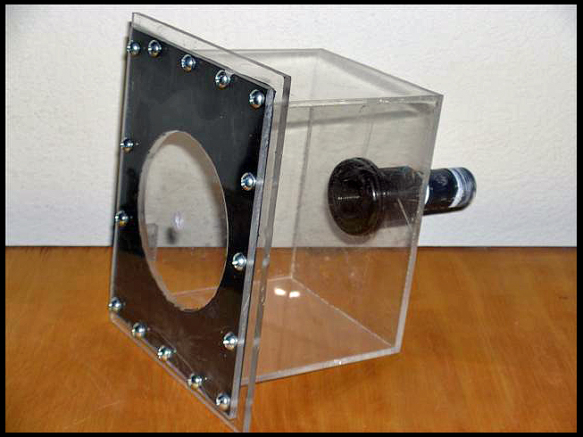
Last edited by Skipper; 04/04/2004 at 11:10 AM. |

|

|
|
11/26/2003, 04:29 PM
|
#2 |
|
Premium Member
Join Date: May 2003
Location: California
Posts: 2,022
|
I took the above shot after I had removed the valves for the second version I will post a photo of shortly. This first attempt worked well except for the 1" pipe at the bottom which didn't allow enough air in at the low water portion of the cycle. Version 2 resolved this issue. So, in the above photo you can see the threaded hole in the top and the black gasket that seals the unit air tight. The hole on the side (just vsible above the top edge of the gasket) is where the Kent float valve is installed. It also has a rubber seal to continue the air tight seal. The other issue with this design was that its internal volume was a little too large. I wanted to make it as small as possible. Enter version #2.
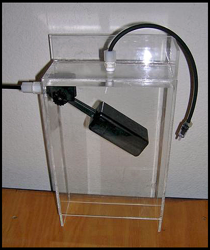 Here you can see I went with a bottomless design and the chamber is just slightly larger that the Kent float valve. I also made one side higher by 1.5" at the bottom. This forces the air entering this side only and allows for leveling so when the air does enter, it's in a "sheet" and in a large quantity. You can also see the Tetra air check valve at the end to the black line that exits through the top of the chamber. The reason for the extension line on this is that the height location of the check valve affects the water upper level and the point where the air escapes the chamber and water within rises, shutting of the float valve. So you are asking yourself "huh?". It goes like this; Water enters through the float valve and empties into the chamber and to the reservoir. It continues and fills the reservoir forcing the air inside the chamber out through the check valve. The water level inside the chamber rises, as the air escapes, and eventually raises the float, shutting off the RO supply line. Now the water within the reservoir starts to empty due to the evaporative need of the aquarium. But the chamber level remains at the top due to the fact that air cannot enter (check valve) to replace the space that would be created by the water level lowering. It just stays put. That is until the water level within the reservoir lowers down enough that the air/water point reaches the bottom side of the chamber. Once it does, air enters and water exits, lowering the top water level and activating the float valve. It then refills and the whole cycle starts over again. Presto! I've been emailing with Turbofish (Brian) as I was going through this and with some not so descriptive clues, he was able to come up with the design but for the check valve. I mention this because he also drew up some really nice drawings showing each stage of the cycle. As soon as I get approval from him to post it, I will do so which should better explain the whole process.
Last edited by Skipper; 04/04/2004 at 11:10 AM. |
|
|
|
|
11/26/2003, 04:33 PM
|
#3 |
|
Premium Member
Join Date: May 2003
Location: California
Posts: 2,022
|
In case it wasn't clear, the chamber is mounted inside a larger container that is the reservoir. I've had this current design running in a make shift reservoir for 3 days now and it's worked flawlessly. I attached a small valve as the output of the reservoir simulating the evaporative water needs (a constant drip) of an aquarium. I'm also feeding the float valve with house water at line pressure so it's still yet to be tested on the slower flow of an RO unit. Obviously, I want to run this for quite some time before I add it to the aquarium and didn't want to waste RO water for this testing. I also need to build a new, larger reservoir. My thought is that once the design is perfected, it could be an integral part of the reservoir, utilizing two walls as part of the chamber. Picture it on one of the inside corners. Alternatively, you could build one similar to my current one that could be added to an existing reservoir with a means to mount it inside.
I also want to add a second, but inline float valve, ahead of the Kent that will mount in the reservoir above the normal high water level. This will work as a backup, safety feature should something malfunction. I could use some help in locating such a valve if anyone knows of such a device. I've yet to find one that is RO/DI safe and has a 1/4" line input as well as output connector. So at this point, I will continue testing this unit and welcome any ideas for improvement. I just wanted to throw this out to get more minds working and to let people know of its inception. I received Brian's approval to post the photo showing the cycles of this system. Here it is and I hope this helps to explain the workings. Thanks to Brian (Turbofish) for the help with ideas and the excellent drawing. 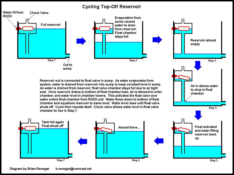
Last edited by Skipper; 04/04/2004 at 11:11 AM. |
|
|
|
|
11/26/2003, 04:37 PM
|
#4 |
|
Premium Member
Join Date: May 2003
Location: California
Posts: 2,022
|
As an update, the current design has been up and running for 4 days now flawlessly. The next step for me is to either purchase a small glass aquarium or build an acrylic version to become my new reservoir. I have the shelf the current 1 gallon unit is on that measures 10" X 24" so this will be the maximum base size. Vertically, I am only limited by the ceiling of about 36" but will need to consider weight as well. If I go the glass route, I will need to drill a hole for the return. I have some diamond bits for my Dremmel tool that should work fine. Also, I'm still looking for an inline float valve to be used as a safety backup but to date have only found the following;
US Plastics Float Valve Web Page Link If any one knows of or can find something similar in design but smaller, please let me know. I don't really want the "toilet" look to this. Basically, I need a small float valve that preferably has an inlet and outlet that will accept the 1/4" RO line and be tolerant of RO/DI water.Last of all, I had done a drawing of the latest chamber version but decided to spruce it up a bit. So here is the result; 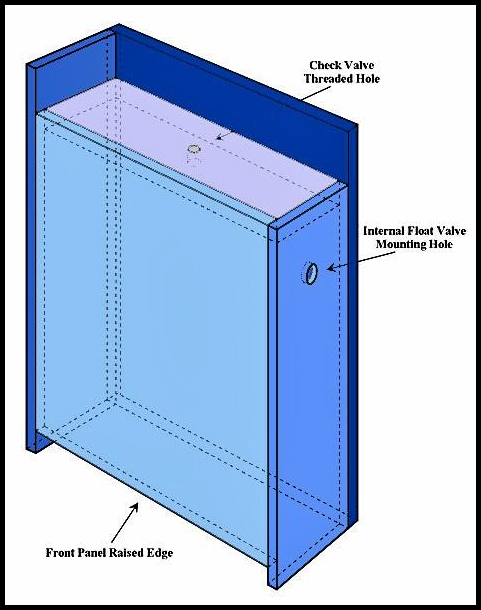
Last edited by Skipper; 04/04/2004 at 11:12 AM. |
|
|
|
|
11/26/2003, 04:41 PM
|
#5 |
|
Premium Member
Join Date: May 2003
Location: California
Posts: 2,022
|
So there you have it. Copied and pasted from my thread but intact none the less. I would appreciate any and all comments, suggestions and input. And if anyone can point me in the direction of a float valve mentioned in the post, I would greatly appreciate that. Regards.
Joseph |
|
|
|
|
11/26/2003, 05:01 PM
|
#6 |
|
Registered Member
Join Date: Oct 2003
Location: Seattle, WA
Posts: 245
|
Very cool idea, tag.
-Erik |
|
|
|
|
11/26/2003, 05:14 PM
|
#7 |
|
Registered Member
Join Date: Jun 2001
Location: Redondo Beach
Posts: 324
|
Great idea! I think you should've kept your original idea using some sort of larger diameter pvc tube on the bottom. That way, the effective length of the device could be adjusted cheaply by just cutting the tube or replacing it with a longer one. Actually, if you could locate a small enough float, you could probably make the whole thing with 6" PVC.
|
|
|
|
|
11/26/2003, 05:30 PM
|
#8 |
|
Pro builder/aquarist hack

Join Date: Jul 2002
Location: NORCAL (Vacaville, CA)
Posts: 5,125
|
Great idea! And well executed!
I usually go with 2 floatswitches and a latching relay, but this is cool! I'm curious why the 1" pvc wouldnt let in enough air. Seems if it got low enough, it would definitely break the vacuum. |
|
|
|
|
11/26/2003, 05:39 PM
|
#9 |
|
Premium Member
Join Date: May 2003
Location: California
Posts: 2,022
|
Macbeth417: Thanks.
gbtower: Thanks and there definitely are cheaper ways of making it. I've even thought that you could use a large diameter PVC T with an end cap that the float would mount to internally. Of course it would have to be large enough to allow for proper travel. Then a simple PVC pipe vertical to the bottom. Personally, I prefer acrylic. I plan to create a reservoir of a given size so I will not need to make any adjustments. In addition, I wanted to eliminate the need for a seal at the top. Thanks again for your comments.H20ENG: Thanks. The reason is that as air enters upward, the water within the chamber drops and dumps into the reservoir area raising its level. This seals the air/water transfer point again and to soon. So not enough air was entering to allow for a "full on" action of the float valve. Instead, it turned on but only at a slow rate. The new design, with its large air/water transfer area, allows a large amount of air (a sheet of) at once and activates the float as planned. Joseph |
|
|
|
|
11/26/2003, 05:43 PM
|
#10 |
|
Pro builder/aquarist hack
Join Date: Jul 2002
Location: NORCAL (Vacaville, CA)
Posts: 5,125
|
I see, thanks. Damn what a cool idea!
I thought of a surge one time using a motor to lift a pipe out of the water til it broke the vacuum and dumped the water. It would have a checkvalve on top so as it submerged, it'd fill again. Pretty tough logistics on building that one. Too many parts. Fun to play with though! Chris |
|
|
|
|
11/26/2003, 05:57 PM
|
#11 |
|
Registered Member
Join Date: Oct 2002
Location: San Diego, California
Posts: 190
|
Is there anyway one of these or something like it could be used?
http://catalog.sensing.honeywell.com...,140876,140877 |
|
|
|
|
11/26/2003, 06:00 PM
|
#12 |
|
Pro builder/aquarist hack
Join Date: Jul 2002
Location: NORCAL (Vacaville, CA)
Posts: 5,125
|
Yes, but they are expensive. Float valves or float switches are the way to go. You can also use differential pressure switches, but float switches are the cheapest. $5-15 each.
|
|
|
|
|
11/26/2003, 06:21 PM
|
#13 |
|
Premium Member
Join Date: May 2003
Location: California
Posts: 2,022
|
Not to mention that my goal was to create a unit void of any electrical devices. Simplicity for reliability.
Joseph |
|
|
|
|
11/26/2003, 06:21 PM
|
#14 |
|
Registered Member
Join Date: Mar 2002
Location: Christiansburg, VA
Posts: 4,893
|
i use a mini carlson surge bucket in my sump to do the same thing. a float switch opens a solenoid which fills a quart-ish sized container that has to fill all the way before a siphon starts that then empties the whole quart at a time into my sump and breaks the siphon for next time.
|
|
|
|
|
11/26/2003, 09:29 PM
|
#15 |
|
Premium Member
Join Date: Oct 2002
Location: just north of Toronto, Canada
Posts: 481
|
Very clever idea....
I need to look at this again without a cold one!! Paul |
|
|
|
|
11/26/2003, 10:17 PM
|
#16 |
|
Registered Member
Join Date: Jul 2002
Location: Houston, Tx
Posts: 2,813
|
That is a great idea, ill have to put that on my list of stuff to do
 Keep us updated as you get to use it. Keep us updated as you get to use it.
__________________
Nick Current Tank Info: 125 Gal Oceanic RR 2 250 Watt Icecap w/ Hamelton 14K |
|
|
|
|
11/26/2003, 10:20 PM
|
#17 |
|
Registered Member
Join Date: Jul 2002
Location: Houston, Tx
Posts: 2,813
|
Oh and I was thinking as a safety device. You can just get one of the electronic type float switches put it at the high point in your reservior and get an always on silinoid that when you apply power it cuts the line off and install that on your incoming water source. So if it gets to high you just cut it off untill you see the problem.
__________________
Nick Current Tank Info: 125 Gal Oceanic RR 2 250 Watt Icecap w/ Hamelton 14K |
|
|
|
|
11/26/2003, 10:39 PM
|
#18 |
|
Premium Member
Join Date: May 2003
Location: California
Posts: 2,022
|
Paul: Thanks and I hope to start building/to buy a reservoir next week and set it up on the tank. The test unit is still plugging away with no issues. It's looking very promising.
 Thanks for the suggestion and yes, that would work well but... I'm still striving to keep this without the aid of any electrical device. It's just a matter of finding the right inline float valve that would work in the exact same way of your suggestion. Essentially a backup, safety device. Thanks again. Thanks for the suggestion and yes, that would work well but... I'm still striving to keep this without the aid of any electrical device. It's just a matter of finding the right inline float valve that would work in the exact same way of your suggestion. Essentially a backup, safety device. Thanks again.Joseph |
|
|
|
|
11/27/2003, 12:02 PM
|
#19 |
|
Registered Member
Join Date: Nov 2003
Location: Alexandria, VA
Posts: 372
|
Joseph,
It would be very interesting to see conductivity readings of your resevoir water before, and after, this new device. We would expect lower values due to the decreased cycling of the RO unit, right?. Just a thought. Ed |
|
|
|
|
11/27/2003, 01:41 PM
|
#20 |
|
Registered Member
Join Date: Feb 2003
Location: Anchorage AK
Posts: 62
|
Did you put the plastic together your-self??
__________________
55g w/110 day power compact & 110 actinic PC, emporor400, power sweep z28, and seaclone 150. +-33 lbs live rock w/ cleaner shrimp, porclin anenome crab, split pair of green bulb anenome, rose bulb anenome, and 7 blue-green chromix. a few black turbo snails, blue and red hermits |
|
|
|
|
11/27/2003, 04:52 PM
|
#21 |
|
Registered Member
Join Date: Nov 2003
Location: Rhode Island
Posts: 407
|
I was under the impression the RO part of the filter was the only thing affected when cycled. The RO spits out impurities as it first starts but wouldn't that just mean shorter DI life? Mute point as this is still bad and having the reservoir setup as described is way cool!

|
|
|
|
|
11/29/2003, 02:44 AM
|
#22 |
|
Premium Member
Join Date: May 2003
Location: California
Posts: 2,022
|
First of all, my previous post was obviously intended for Nick and not Paul. Sorry about that.
Ed: Yes, you are right. I am expecting lower readings. Measurements will be conducted but I need to contact Charles of SpectraPure for suggestions on how best to accomplish this. I do have a TDS meter that was originally part of my RO/DI unit but I'm not sure if its accuracy is good enough to give concrete evidence or not. I do know that it has dipswitches inside for adjusting its sensitivity though so perhaps this can be utilized. Thanks for the suggestion. wanabeeReeFeR: Yes, I cut and assembled the acrylic myself. I've been working with this since I started in this hobby, about 9 years now, but I'm still learning. thorsky: That is correct, the RO filter is the culprit. It's true that you can add more DI units to try to alleviate the problem but this can get very costly. In addition, I already run two so it would be nice if they were to last longer. I think it better to attempt to alleviate the problem, or at least minimize it as much as possible, as apposed to throwing money at it knowing you will have to live with it. Joseph |
|
|
|
|
11/29/2003, 07:04 AM
|
#23 |
|
Registered Member
Join Date: Nov 2003
Location: Alexandria, VA
Posts: 372
|
Joseph,
I've played with the spectrapure meter - there are a few levels of sensitivity beyond where I have it set - but using that to measure for this experiment would be a challenge. Sounds like justification for a conductivity meter!
|
|
|
|
|
12/07/2003, 11:32 AM
|
#24 |
|
Registered Member
Join Date: Jul 2002
Location: Houston, Tx
Posts: 2,813
|
weatherson,
Have you had any need to do maintance to that kent flot valve you are using inside the chamber? I was thinking of making my chamber with alittle less acrylic but I would never be able to access the float valve without cutting up the chamber.
__________________
Nick Current Tank Info: 125 Gal Oceanic RR 2 250 Watt Icecap w/ Hamelton 14K |
|
|
|
|
12/07/2003, 03:06 PM
|
#25 |
|
Premium Member
Join Date: May 2003
Location: California
Posts: 2,022
|
Nick: While I haven't ever needed to gain access to the float valve in my current reservoir (~ 5 years now), I went with a design so I could.
The inside width and depth of my chamber is 1/4" larger than that of the valve and runs this size all the way down. There's no reason you couldn't go smaller and enclose the valve as long as the bottom opening is large enough to provide a long, straight access point for the air to "sheet" in and provide a large enough amount to properly actuate the valve. The chamber size seems to not be as critical as the this design of the bottom opening. Out of curiosity, can you describe your design thoughts? Thanks.Joseph |
|
|
|
 |
|
|


