|
|
|
|||||||
 |
| Thread Tools |
 10/05/2013, 08:21 PM
|
#1 |
|
Registered Member
Join Date: May 2008
Location: Canada
Posts: 159
|
LED Full Spectrum Controller based on Mega2560 board
8 Channels LED controller based on Arduino Mega2560 with 3.2" TFT touch screen panel.
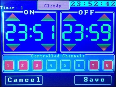
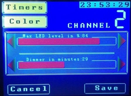
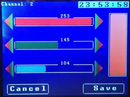
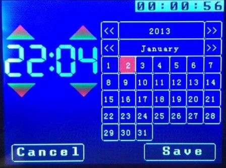
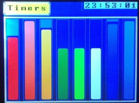
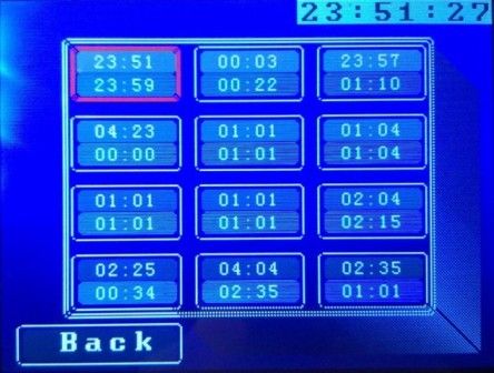
Always was thinking to control spectrum of the light to avoid algae problem. With LED it's easy to do. This device was designed for full LED spectrum control. Level of each channel can be adjusted 0-100% of LED power. This project try to focus on: 1. "As cheap as possible", and it looks like it is, please see bellow. 2. Easy to build as: - get parts - load software - enjoy Video of working controller Download the latest version from here Software: loader and .hex file for arduino There are 2 files: one for ILI touchscreen another for ITBD Main screen:  LED level setup screen  Doser setup screen  Average cost of the project: Arduino Mega2560 = $15 TFT 3.2" = $10 Shield between arduino and TFT = $10 ---- Minimum configuration that will work: $35 With drivers, power supply + box about $150 Last edited by kapelan; 10/04/2017 at 08:55 PM. Reason: pictures are not loaded |

|

|
|
10/05/2013, 08:46 PM
|
#2 |
|
Head zoo keeper
Join Date: Nov 2005
Location: Toledo ,Ohio
Posts: 710
|
looks very nice where did you get the box for the controller
also where did you get the board with all the drivers on it looks like the driver board plugs in to the mega? Last edited by rott; 10/05/2013 at 08:58 PM. |
|
|
|
|
10/05/2013, 09:32 PM
|
#3 |
|
Premium Member
 Join Date: Jun 2003
Location: Cleveland, Ohio
Posts: 857
|
Me likes very much. Can we see a picture with the tft removed? Are you worried about heat build up with the psu on top of each other?
__________________
With a Router and a Table saw you can make anything for your tank. |
|
|
|
|
10/05/2013, 10:14 PM
|
#4 |
|
Registered Member
Join Date: May 2008
Location: Canada
Posts: 159
|
That's a sandwich:
Arduino + Shield + TFT All drivers are on the shield View from bottom: 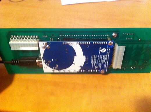 Front panel laser cut from transparent acrylic. Back panel laser cut from stainless steel. Box from ebay. No hot places on these boards. Drivers are also cold. Last edited by kapelan; 10/05/2013 at 10:16 PM. Reason: add |
|
|
|
|
10/05/2013, 11:34 PM
|
#5 |
|
Registered Member
Join Date: May 2008
Location: Canada
Posts: 159
|
|
|
|
|
|
10/05/2013, 11:42 PM
|
#6 |
|
Registered Member
Join Date: Apr 2011
Location: Cupertino, CA
Posts: 1,111
|
Looks good. But when you spent the money on a PCB with drivers, why not just use a TI chip to make it into a 16-channel 12-bit controller instead of an 8-channel?
|
|
|
|
|
10/05/2013, 11:49 PM
|
#7 | |
|
Registered Member
Join Date: May 2008
Location: Canada
Posts: 159
|
Quote:
I remember one chip for 16 channel LED array but it supports current 50-300mA or so. That is definitely not enough. |
|
|
|
|
|
10/06/2013, 01:37 AM
|
#8 | |
|
Registered Member
Join Date: Apr 2011
Location: Cupertino, CA
Posts: 1,111
|
Quote:
The TLC5940 is what I'm thinking of. AdaFruit sells a board for it. |
|
|
|
|
|
10/06/2013, 11:23 AM
|
#9 |
|
Registered Member
Join Date: May 2008
Location: Canada
Posts: 159
|
bunch of boards means bunch of connections and wires.
This design is good for temporary testing. For permanent solution it must be only one board. |
|
|
|
|
10/06/2013, 04:37 PM
|
#10 | |
|
Registered Member
Join Date: Apr 2011
Location: Cupertino, CA
Posts: 1,111
|
Quote:
|
|
|
|
|
|
10/17/2013, 07:35 AM
|
#12 |
|
Registered Member
Join Date: May 2008
Location: Canada
Posts: 159
|
I'm thinking about improving this device and add PH and ORP control.
this is the project of main screen: 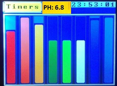 PH and ORP will be flashing, like 3-5 seconds display ORP and then 3-5 seconds display PH level. PCB can be ordered minimum 10 peaces, and I need only one. The size of PCB: 10x25 cm Does anybody interested in this PCB? Last edited by kapelan; 10/17/2013 at 07:36 AM. Reason: spel |
|
|
|
|
10/17/2013, 07:46 AM
|
#13 |
|
Head zoo keeper
Join Date: Nov 2005
Location: Toledo ,Ohio
Posts: 710
|
you also hand made the driver's to right?
|
|
|
|
|
10/17/2013, 07:58 AM
|
#14 |
|
Registered Member
Join Date: May 2008
Location: Canada
Posts: 159
|
Drivers on board - last picture from the topic.
Board will be the same size with everything on it: - timer - 8 drivers - ORP - PH Just reorganized for ORP and PH chips |
|
|
|
|
10/17/2013, 12:31 PM
|
#15 | |
|
Registered Member
Join Date: Feb 2003
Location: Helsinki - Finland
Posts: 19
|
Quote:
|
|
|
|
|
|
10/25/2013, 10:18 PM
|
#16 |
|
Registered Member
Join Date: May 2008
Location: Canada
Posts: 159
|
|
|
|
|
|
11/06/2013, 10:56 PM
|
#17 |
|
Registered Member
Join Date: Nov 2013
Posts: 1
|
do have one extra pcb you want to sell
|
|
|
|
|
11/07/2013, 06:47 PM
|
#18 |
|
Registered Member
Join Date: Mar 2005
Location: St. Louis, MO.
Posts: 3,259
|
Very nice!
Have you had it running full power yet? As someone else asked aren't you worried the PSUs will over heat with no cooling of the enclosure? They are intended for free air convection not sealed in a box..... Drivers, even the really efficient type get hot too running in a sealed box, but maybe not the 100+C needed to cause any problems as long as they don't melt something else...... |
|
|
|
|
11/10/2013, 08:45 PM
|
#19 |
|
Registered Member
Join Date: May 2008
Location: Canada
Posts: 159
|
It is running on 27V 8 channels 1A each, so total it's about 200W
LEDs used mostly CREE. Light time 7 hours. Nothing is worm inside. Driver can support up to 40V - for test reason I tried 36V - they are cold and working fine. So basically device can do 40V x 1A x 8 channels = 320W. That's a lot! The only reason I did not do it - Power Supply from meanwell costs a lot. And chinese power supply with this voltage from ebay are big to fit the box. Last edited by kapelan; 11/10/2013 at 08:49 PM. Reason: corrected |
|
|
|
|
01/18/2014, 10:56 PM
|
#20 |
|
Registered Member
Join Date: May 2008
Location: Canada
Posts: 159
|
full version
created full version, video:
http://www.youtube.com/watch?v=YFApA...ature=youtu.be PH control ORP control Temperature control Overflow (4 sensors) 8 power lines 8 led channels |
|
|
|
|
01/19/2014, 04:23 AM
|
#21 |
|
Registered Member
Join Date: Nov 2011
Location: Keighley West Yorkshire
Posts: 101
|
Nice one were did you get the PCB from ?
|
|
|
|
|
01/20/2014, 09:09 AM
|
#22 |
|
Registered Member
Join Date: May 2008
Location: Canada
Posts: 159
|
PCB/schema designed by myself.
PCB fabrication from china. |
|
|
|
|
01/20/2014, 09:35 AM
|
#23 |
|
Registered Member
Join Date: Nov 2011
Location: Keighley West Yorkshire
Posts: 101
|
Very Impressed dude looks very Good

|
|
|
|
|
01/20/2014, 11:32 AM
|
#24 |
|
Registered Member
Join Date: May 2008
Location: Canada
Posts: 159
|
Bom
Thank you,
I like it too  Attached BOM of the project. Some items from digikey , some from ebay. because do not agree with the of price from digikey
Last edited by kapelan; 01/20/2014 at 11:33 AM. Reason: edit |
|
|
|
|
01/20/2014, 03:50 PM
|
#25 |
|
Registered Member
Join Date: Nov 2011
Location: Keighley West Yorkshire
Posts: 101
|
Thanks Dude
|
|
|
|
|
| Tags |
| aquarium controller, arduino, led, led controller |
|
|