|
|
 06/12/2012, 07:59 PM
|
#4801 | |
|
Registered Member
Join Date: Jul 2004
Location: AWOL
Posts: 12,013
|
Quote:
The big issue i see is with the pump intake. With your configuration, there is insufficient distance from the elbows to the intake. It lacks the straight length necessary for the turbulence caused in the elbows, to calm down before entering the pump volute. This can and does cause a pump to cavitate. The rule is 15 x the inside pipe diameter, however, often 7 - 10x the inner diameter can keep the pump from cavitating.  Also, i think you would be better served with a single return line, up and in , rather than up over up split dual in -- this will only decrease your pump performance, and you are not gaining anything by splitting the return at the tank. Also would upsize the return plumbing. 1" looks a bit small for that pump: assuming a 1" pump outlet.
__________________
"Things should be made as simple as possible, but not simpler." (oft attributed to Einstein; most likely paraphrasing by Roger Sessions; compactly articulates the principle of Occam's Razor) Current Tank Info: 325 6' wide Reef Last edited by Misled; 11/01/2017 at 06:28 PM. |
|

|

|
|
06/13/2012, 08:06 PM
|
#4802 |
|
Registered Member
Join Date: Jun 2000
Location: El Paso, TX, USA
Posts: 1,549
|
Is there a reason why bean decided to reduce the size of his bulk head and his elbows inside of his tank instead of using 1.5" throughout?
|
|
|
|
|
06/13/2012, 08:07 PM
|
#4803 |
|
Registered Member
Join Date: Jun 2011
Location: South Texas
Posts: 2,159
|
I think he said he already had 1" bulkheads or something along those lines.
__________________
-You had me at PWM |
|
|
|
|
06/13/2012, 08:56 PM
|
#4804 | |
|
Registered Member
Join Date: Jun 2000
Location: El Paso, TX, USA
Posts: 1,549
|
Quote:
|
|
|
|
|
|
06/13/2012, 09:18 PM
|
#4805 |
|
Registered Member
Join Date: Feb 2003
Location: Pittsburgh
Posts: 20,772
|
Rico,
The tank was already drilled for (3) 1" "durso" style standpipes. I fiddled with them for weeks trying to keep them in tune. This design was born party out of that frustration and partly out of the backlash from at least (2) floods and a few near misses. I upsized the pipe for the open channel to allow more room for open channel flow. In the process, I built all (3) pipes the same size. The larger diameter siphon and emergency both enhance the overall capacity and safety of the system as well. |
|
|
|
|
06/13/2012, 09:20 PM
|
#4806 |
|
Registered Member
Join Date: Jun 2011
Location: South Texas
Posts: 2,159
|
I did on my 210. I was also using a reeflo dart/snapper though, so the flow rate was 2000~ GPH and I still had to shut the siphon valve more than I would have expected. Even at that, I think 2000 GPH through the sump is more than you would want for skimming purposes anyways. In my mind, I think you are okay to go that big if the flow is sufficient enough. My reasoning is that if you go 1.5" and try to run a siphon on a low throughput, say 500 GPH, it may not work very well since the plumbing is so large it may have issues creating the necessary pressure for a siphon due to air build up in the large plumbing; might be some unwanted cavitation. My knowledge on fluid dynamics is not to the expert level, so I may be wrong. However, my recommendation would be to go with a something like 1" and shoot for 500-1000 GPH through the sump. The 1" will handle that easily.
__________________
-You had me at PWM |
|
|
|
|
06/13/2012, 09:37 PM
|
#4807 | |
|
Registered Member
Join Date: Jun 2000
Location: El Paso, TX, USA
Posts: 1,549
|
Quote:
|
|
|
|
|
|
06/13/2012, 09:41 PM
|
#4808 | |
|
Registered Member
Join Date: Jun 2000
Location: El Paso, TX, USA
Posts: 1,549
|
Quote:
|
|
|
|
|
|
06/13/2012, 09:54 PM
|
#4809 |
|
Registered Member
Join Date: Jun 2011
Location: South Texas
Posts: 2,159
|
It's possible. Just be aware I did the same. Gate valve is definitely the way to go, but even at that with 1.5" I am estimating I had to close it 50% to tune the system at around 2000 GPH.
BTW, Go Miners! 
__________________
-You had me at PWM |
|
|
|
|
06/13/2012, 10:03 PM
|
#4810 |
|
Registered Member
Join Date: Jun 2000
Location: El Paso, TX, USA
Posts: 1,549
|
Rasco really? You had to dial it that far down? Ok I am going with 1".
. I like that picture. Do you have more pictures of your set up? They speak a 1000 words.
|
|
|
|
|
06/13/2012, 10:08 PM
|
#4811 |
|
Registered Member
Join Date: Jun 2011
Location: South Texas
Posts: 2,159
|
Yeah, I am just estimating, but it was much more than I intended. I think Bean's original article says it should handle 2000~ GPH at 1", so that should be more than sufficient for anything you throw at it.
You can get more details about the BROKEN 210 here. At the end of the thread there is a link to the replacement 105 thread where I also used the bean drain with 1" drains; works amazingly (Thanks Bean!): http://www.reefcentral.com/forums/sh...php?p=19714398
__________________
-You had me at PWM |
|
|
|
|
06/13/2012, 10:51 PM
|
#4812 |
|
Registered Member
Join Date: Feb 2003
Location: Pittsburgh
Posts: 20,772
|
Your Welcome
Sorry to hear about the loss of the tank! |
|
|
|
|
06/13/2012, 11:49 PM
|
#4813 | |
|
Registered Member
Join Date: Apr 2012
Location: Sandy Eggo
Posts: 197
|
Quote:
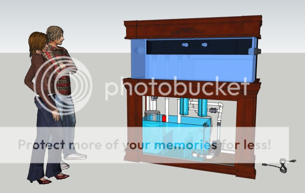
First off, at the moment, I don't know if I can consider myself truly in the aquarium hobby as I only have a bare tank in my possession; no other equipment or livestock. I'm just in the preliminary design stage to allow me to accurately forecast all necessary equipment, supplies and tools (just picked up a miter saw and jointer for the cabinetry work) and plan a budget and project timeline accordingly. Due to the expenses, I think it will be at least 6 months or more before I'm actually ready to get a reef tank underway. No doubt I will start such a thread once I've physically "knee deep", but don't want to "false start" such a build thread in case something sidetracks me before I truly begin... On to the points raised. Unfortunately, as in life, everything is a compromise  No way I could get a straight shot into the pump without removing the valve (requiring full drainage of return stage of sump for pump maintenance) and/or removing the flexible tubing (want to limit any vibration that could lead to premature failure of the sump and elevated sound levels--the intent is for a COMPLETELY SILENT aquarium!), or reducing the length of the standard 36" sump as all compartments are already at minimum sustainable lengths, including the skimmer stage. And this is in a 5 foot long x 2 foot deep cabinet too (don't know if you noticed that part of the cabinet has a bulkhead separating the equipment compartment from the electrical compartment). I chose 5x2 specifically since a 4x cabinet absolutely would not fit all my intended equipment and 6 foot plus and/or 3 foot deep is just too long/large for any foreseeable aquarium location. The absolute criteria that can not be deviated from is that everything must fit within the cabinet, including Auto-Top Off system; no ifs ands or butts! Believe me, I tried every way to make it a straight shot into the pump. No way I could get a straight shot into the pump without removing the valve (requiring full drainage of return stage of sump for pump maintenance) and/or removing the flexible tubing (want to limit any vibration that could lead to premature failure of the sump and elevated sound levels--the intent is for a COMPLETELY SILENT aquarium!), or reducing the length of the standard 36" sump as all compartments are already at minimum sustainable lengths, including the skimmer stage. And this is in a 5 foot long x 2 foot deep cabinet too (don't know if you noticed that part of the cabinet has a bulkhead separating the equipment compartment from the electrical compartment). I chose 5x2 specifically since a 4x cabinet absolutely would not fit all my intended equipment and 6 foot plus and/or 3 foot deep is just too long/large for any foreseeable aquarium location. The absolute criteria that can not be deviated from is that everything must fit within the cabinet, including Auto-Top Off system; no ifs ands or butts! Believe me, I tried every way to make it a straight shot into the pump.  If you have any suggestions, I'm definitely all ears! By the way, the inlet is 1" and the distance from the centerline of the last elbow to the front face of the pump intake is approximately 8-1/2" (9-1/2" if measuring all the way to the impeller blades), so that would seem to meet your minimum 7-10x cavitation prevention rule. This is why I love CAD! If you have any suggestions, I'm definitely all ears! By the way, the inlet is 1" and the distance from the centerline of the last elbow to the front face of the pump intake is approximately 8-1/2" (9-1/2" if measuring all the way to the impeller blades), so that would seem to meet your minimum 7-10x cavitation prevention rule. This is why I love CAD!Regarding the pump, I'm going with the Snapper, so with guestimated head losses putting me at around 1,500-1,700 GPH, the 1" should be sufficient from all that I've gleaned of flow rates of various pipe sizes. If not, then I can always valve down as I will probably include a valve on the pump output in my final design, which may possibly help with any cavitation issues with lower flow through the "180" intake. The "over" return line portion was to allow for a custom top off tank immediately below the external overflow; a compromise that favors incorporating a gravity fed top off over any slight head loss due to a more circuitous route for the return. The "through" return lines were decided upon due to several reasons: 1) to allow the canopy to be removable without having to undo the Loc-Lines if I went the "up and in". It is not shown but the front part of the canopy is hinged and exposes the front rim of the tank completely; the only support is on the sides and along the full width of the rear rim. 2) I will be fully blocking the rear above the rim to prevent light from getting to the external overflow as well as to prevent light from escaping out the back and shining on the wall directly behind where the aquarium is up against. Finally, Loc-Lines are only offered as large as 3/4", hence my splitting of the 1" into a pair of 3/4" Loc-Lines; better than going from 1" to a single 3/4", or even worse, some unsightly plain 1" piping poking out. It certainly doesn't hurt having the split, yet it does look more symmetrical in design having a pair of Loc-Lines spewing forth and does offer me greater flexibility in adjusting flow output in multiple directions if need be. Besides, I'm not concerned about attempting to reach an absolute return GPH target number since I'm going with a very capable high flow pump. It already seems quite clear from other's experiences that the siphon drain typically has to be closed quite a bit on 1.5" drains fed by Reeflo Snappers/Darts, so any additional head losses from a more complex return route shouldn't have any adverse effect. That's just my opinion at the moment, of course. Only after I've built it will I know for sure! Last edited by Augster; 06/14/2012 at 12:39 AM. |
|
|
|
|
|
06/16/2012, 11:10 AM
|
#4814 |
|
Registered Member
 Join Date: Nov 2008
Location: Houston, TX
Posts: 10,344
|
My tank is against the wall (internal coast to coast) and my beananimal plumbing is on the other side of the wall in the garage. So I have a 6" horizontal span between the bulkhead and the 1.5"x1" slip bushing on the beananimal drain. I know the system wasn't designed to have this extra 6" horizontal run but does anyone foresee any problems I should be aware of? I would think once the pipe is filled and the siphon starts it shouldn't be an issue.
__________________
-dennis Elos Diamond 120xl | Elos Stand | Radion G4 Pros | GHL Profilux Controller | LifeReef Skimmer | LifeReef Sump Photos taken with a Nikon D750 or Leica M. |
|
|
|
|
06/16/2012, 11:30 AM
|
#4815 | |
|
Moved On
Join Date: Jun 2012
Location: Carrollwood Tampa
Posts: 177
|
Quote:

|
|
|
|
|
|
06/16/2012, 11:40 AM
|
#4816 |
|
Registered Member
Join Date: Nov 2008
Location: Houston, TX
Posts: 10,344
|
Ya, i thought about it but i don't have much of a drop on the other side of the wall to my big rubbermaid sump which is elevated, so i figured i'd save the couple inches of drop through the wall so I could maximize drop on the other side. Not sure if it really makes a difference either way.
__________________
-dennis Elos Diamond 120xl | Elos Stand | Radion G4 Pros | GHL Profilux Controller | LifeReef Skimmer | LifeReef Sump Photos taken with a Nikon D750 or Leica M. |
|
|
|
|
06/17/2012, 07:42 AM
|
#4817 |
|
Registered Member
Join Date: Jun 2012
Posts: 1
|
First of all, thank you to Bean for his knowledge and help to all of us reading this thread.
I have spent the last 3 days reading the first 30 pages of the original thread and now find out there are 193 more to go! I am actually from Australia so usually post on the MASA forums however I've read quite a lot of info on RC of late. I only have 1 simple question which I am sure has been covered already. How far off the bottom of the coast to coast overflow box does the bottom of the street elbow need to be on the siphon and open pipe? Is there a minimum/maximum or ideal height? Thanks in advance. |
|
|
|
|
06/17/2012, 08:05 AM
|
#4818 | |
|
Registered Member
Join Date: Nov 2008
Location: Houston, TX
Posts: 10,344
|
Quote:
Speaking of which, does anyone have tips on cutting those grooves? I have a table saw and a tabletop circular saw, but not sure how to go about it without loosing fingers. And per my question above about the horizontal flow, I hope it works cause it's now plumbed!
__________________
-dennis Elos Diamond 120xl | Elos Stand | Radion G4 Pros | GHL Profilux Controller | LifeReef Skimmer | LifeReef Sump Photos taken with a Nikon D750 or Leica M. |
|
|
|
|
|
06/18/2012, 07:50 AM
|
#4819 |
|
Registered Member
Join Date: Nov 2008
Location: Houston, TX
Posts: 10,344
|
Here's how my drain plumbing turned out.
Just need to run the airline back through the wall to the tank. 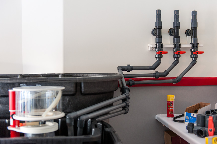
__________________
-dennis Elos Diamond 120xl | Elos Stand | Radion G4 Pros | GHL Profilux Controller | LifeReef Skimmer | LifeReef Sump Photos taken with a Nikon D750 or Leica M. |
|
|
|
|
06/18/2012, 08:13 AM
|
#4820 |
|
Registered Member
Join Date: Apr 2012
Location: Sacramento, CA USA
Posts: 238
|
Wow. Must be nice to have so much room for the equipment. Very clean work. Looks GREAT!
__________________
Waggs Tank info: Size = 100 gallons, 48" long, 18" wide and 24" deep. Sump Info: 20 gallon long converted with baffles installed. EMI 3100 return pump with a head pressure of about 960 GPH |
|
|
|
|
06/18/2012, 09:51 AM
|
#4821 |
|
Moved On
Join Date: Jun 2012
Location: Carrollwood Tampa
Posts: 177
|
Dennis, You did a really nice job cutting and fitting the 3 PVC runs the way you did. Very clean indeed.
Do you have a pic of your overflow setup from the tank side of the wall? Curious to see the entire drain plumbing setup. |
|
|
|
|
06/18/2012, 10:09 AM
|
#4822 |
|
Registered Member
Join Date: Nov 2008
Location: Houston, TX
Posts: 10,344
|
Thanks! Hopefully it works!
The only pics i have of the overflow right now are in my build thread, bottom of this page. http://www.reefcentral.com/forums/sh...2144250&page=3 Pics don't show it plumbed yet but all you'll see from this side are the bulkheads and the elbows. Speaking of elbows, if anyone has tips on cutting the teeth on the one end of the elbows, let me know!
__________________
-dennis Elos Diamond 120xl | Elos Stand | Radion G4 Pros | GHL Profilux Controller | LifeReef Skimmer | LifeReef Sump Photos taken with a Nikon D750 or Leica M. |
|
|
|
|
06/19/2012, 08:35 AM
|
#4823 | |
|
Registered Member
Join Date: Aug 2009
Location: Northern VA
Posts: 4,618
|
Quote:
__________________
Click my home page for Thread Summaries Current Tank Info: 75 gallon lps and fish |
|
|
|
|
|
06/19/2012, 04:03 PM
|
#4824 |
|
Registered Member
Join Date: Feb 2003
Location: Pittsburgh
Posts: 20,772
|
To make sure there is no confusion...
There were "teeth" in the elbows on the prototype. My elbows no longer have teeth. I don't feel (in retrospect) that they are needed and are far to dangerous to easily cut with the power tools that most folks have access to. |
|
|
|
|
06/19/2012, 04:05 PM
|
#4825 | |
|
Registered Member
Join Date: Aug 2011
Location: Star, ID
Posts: 84
|
Quote:
|
|
|
|
|
 |
| Tags |
| beananimal, plumbing |
|
|