|
|
|
|||||||
 |
| Thread Tools |
 04/02/2010, 10:53 PM
|
#1 |
|
Registered Member
Join Date: May 2008
Location: Durham, NC
Posts: 2,205
|
Taqpol's DIY LED prototype build, detailed pictures
In May I am going to be moving to North Carolina and upgrading my tank at the same time. As of now the current plan is to have a 180 gallon tank lit with four blocks of 24 3w Cree XR-E's (spotlighting two major islands) and another one or two strips of 24 LEDs for coverage in the middle of the tank. On top of all of that I am contemplating building my own Arduino controller and using 8 channels of PWM to simulate sunrise and sunset over the reef. Before I got too deep into all of this I wanted to build my own test fixture so I could actually hold it in my hands to see what was what.
I ordered a 24 LED (12 cool white, 12 royal blue) kit from www.rapidled.com and an 8.4"x10" aluminum heatsink from www.heatsinkusa.com on Monday night and both packages arrived here today! The LEDs will be driven by two Meanwell ELN-60-48P drivers. 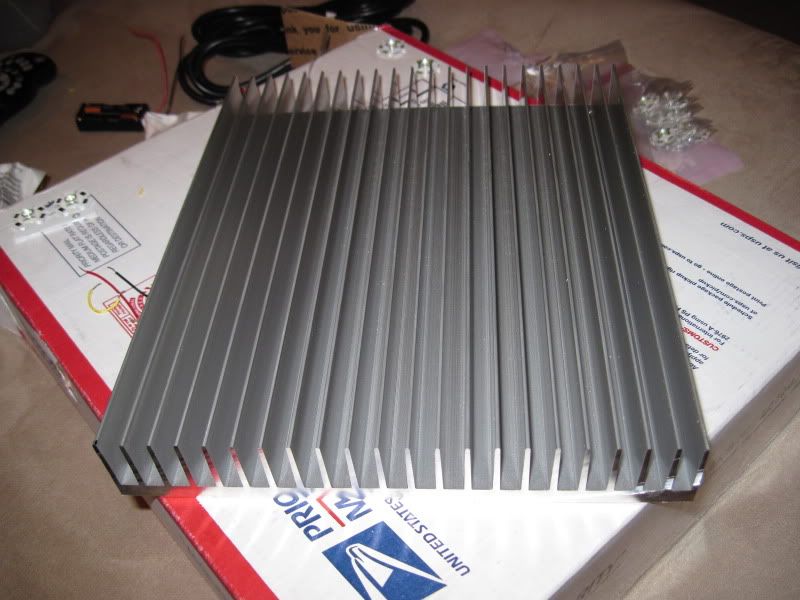   I already have a question about dimming though. Can dimmable Meanwell drivers be ran (in a constant current mode) if I don't have anything attached to the DIM + and - leads? I want to be able to dim this puppy in the future, but right now i just want to get it set up and running.
__________________
^ Click on my username and 'Visit Taqpol's Home Page!" to view my 220 gallon custom Miracles tank! -Alex |

|

|
|
04/02/2010, 11:02 PM
|
#2 |
|
Registered Member
Join Date: May 2008
Location: Durham, NC
Posts: 2,205
|
Also, when building dimming circuits I have heard that you have to go inside the meanwell and adjust an internal pot that controls the maximum current. I think that pot is this one next to where the LED and dimming cables exit the fixture:
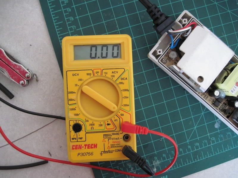
 Can someone confirm that for me? Lastly, this is my multimeter and while I am somewhat electronics illiterate I'm pretty sure it only goes up to 200 mA max:  Since I will want my max amperage to be at least 700 mA do I need to find a new multimeter? Can someone suggest a good yet cheap one I might be able to pick up at a local store?
__________________
^ Click on my username and 'Visit Taqpol's Home Page!" to view my 220 gallon custom Miracles tank! -Alex |
|
|
|
|
04/02/2010, 11:21 PM
|
#3 |
|
Registered Member
Join Date: Oct 2009
Location: VA
Posts: 843
|
where are you moving to in NC?
__________________
_____________ |
|
|
|
|
04/02/2010, 11:27 PM
|
#4 | |
|
Registered Member
Join Date: May 2008
Location: Durham, NC
Posts: 2,205
|
I'm also going to post this here just so I don't forget what page of the massive DIY LED thread its on. A very good description of how to solder LEDs on stars by RC member kcress:
Quote:
Aaaaaand I have yet another question. I have 20g wire laying around that seems perfect, but should I use stranded or solid wire for wiring between the LED stars?
__________________
^ Click on my username and 'Visit Taqpol's Home Page!" to view my 220 gallon custom Miracles tank! -Alex Last edited by Taqpol; 04/02/2010 at 11:40 PM. |
|
|
|
|
|
04/02/2010, 11:28 PM
|
#5 | |
|
Registered Member
Join Date: May 2008
Location: Durham, NC
Posts: 2,205
|
Quote:
__________________
^ Click on my username and 'Visit Taqpol's Home Page!" to view my 220 gallon custom Miracles tank! -Alex |
|
|
|
|
|
04/02/2010, 11:29 PM
|
#6 |
|
Drug Enthusiast
Join Date: Oct 2007
Location: Rochester, MN
Posts: 2,958
|
Looks like you're off to a great start. As far as I know, your multimeter is just fine. Simply turn the dial to the "10A" option which is in its own little red-lined section. Then physically unplug your red lead and plug it into that corresponding socket. All you have to do is wire up your LEDs and break the connection, connecting in the multimeter in series as if it were just another LED.
I'm not sure if you are questioning, but I'm guessing that no active cooling will be necessary considering the heat sinking that's going on 
|
|
|
|
|
04/02/2010, 11:39 PM
|
#7 | |
|
Registered Member
Join Date: May 2008
Location: Durham, NC
Posts: 2,205
|
Quote:
I will definitely be actively cooling with some kind of computer fan hooked to a wall wart, but for right now I am more concerned about figuring out the wiring of the meanwell.
__________________
^ Click on my username and 'Visit Taqpol's Home Page!" to view my 220 gallon custom Miracles tank! -Alex |
|
|
|
|
|
04/03/2010, 12:44 AM
|
#8 |
|
Premium Member
 Join Date: Oct 2007
Location: Cary, NC
Posts: 3,760
|
If in doubt about the 200ma max thing, there is another, probably more accurate way to measure current with that multimeter, but you will need a resistor. A 1% tolerance 0.1ohm resistor is best, but you can also use a 1ohm or 1/2 ohm since 0.1 ohm is likely not at Radio Shack.
Hook the resistor up in series with your LEDs. Connect your multimeter probes to both ends of the resistor, and read the voltage in mv. Current = Voltage / Resistance I = V / R So if you have a 1ohm resistor (what I used), then the reading (in mV) will actually be the direct reading of mA (current). If you used a 0.1 ohm resistor, you multiply the value by 10 first... just plug your mV reading and resistor ohms into that equation. Also note that a 1% tolerance resistor need not be used. Regardless, you should set the multimeter to the ohms setting and measure the ohms of your resistor first, which should take the guesswork out of it, especially if you had to settle for a 10% resistor which is more common. Wish I could help with the question about running the PWM meanwells without a dimming signal but I haven't messed with em yet, just the buckpucks. I'd recommend stranded wire between LEDs, it puts less stress on the solder joints and IMO is just easier to work with. I did use solid wire on the first and last connection of each of my LED strings since that's what my quick disconnects needed, and it does seem to work just fine. 20g sounds fine; I used it in between my stars. Kcress will tell you to go higher gauge like 22-24, but stugray, myself and others have used thicker wire like 18g and it works just fine, but Kcress probably does have a point about thicker wires putting unnecessary stress on the stars/solder joints. Thicker wire is only really beneficial if we are talking about long wire runs, so I wouldn't go with beefy wire between the LEDs. good luck!
__________________
- Ryan B "that is enough skimmate to ruin lives." - GSMguy Current Tank Info: 220g Display, 70g sump, 35g frag, 50g fuge, 2x250w MH, 1x400w MH, 2x80w T5, 2x140w VHO Actinic Last edited by ReefEnabler; 04/03/2010 at 12:54 AM. |
|
|
|
|
04/03/2010, 12:57 AM
|
#9 |
|
Registered Member
Join Date: Jul 2007
Location: Puerto Rico
Posts: 673
|
I'm pretty sure you won't get accurate results by testing the meanwell without being hooked to the whole rig. It will auto adjust. It is recommended to turn down the SRV2 pot to the lowest (~700ma) then adjust and measure while having all the LEDs connected (make sure you don't break it though. It only turns around 270 degrees side to side. I though it was like a screw and turned like 200 times lol) You can get constant current from it by just pluging the DIM -, + wires to a 10V max power supply. I'm currently using 9V wall wart while I get something to Dim with. You could even use a 9V battery.
|
|
|
|
|
04/03/2010, 01:01 AM
|
#10 |
|
Premium Member
Join Date: Oct 2007
Location: Cary, NC
Posts: 3,760
|
ooo I like the 9v battery idea
__________________
- Ryan B "that is enough skimmate to ruin lives." - GSMguy Current Tank Info: 220g Display, 70g sump, 35g frag, 50g fuge, 2x250w MH, 1x400w MH, 2x80w T5, 2x140w VHO Actinic |
|
|
|
|
04/03/2010, 01:04 AM
|
#11 |
|
Registered Member
Join Date: Jul 2007
Location: Puerto Rico
Posts: 673
|
yeah works very good. I had a 72 LED lamp On for more than an hour with one of those
Also have toyed with AA's to get "dimmed" effects. Also a poor man's dimmer could be a multi-voltage power supply. Ranges from 2.4V to 12V. Just need to make sure you don't crank it up to 12V |
|
|
|
|
04/03/2010, 01:08 AM
|
#12 |
|
Registered Member
Join Date: Dec 2007
Location: Central California Coast.
Posts: 5,383
|
The MW needs to be hooked up and running the LEDs before you bother trying to "dial it in". Do however turn it DOWN before powering up your string with it the first time.
Widmer has the meter setup explained well. Follow that. A warning. Remember not to power the MW and then close the circuit on your string. It will FLASH ONCE and that will be the end of it. This can easily happen when you are measuring the current by breaking the string and inserting a meter. Then you get the bright idea to remove the meter (string now open) then you re-hook the wires to get the string back on without actually turning off the power first... FLASH! I doubt you'll need any fan on that sink at all if air can flow easily across it. |
|
|
|
|
04/03/2010, 08:21 AM
|
#13 | |
|
Registered Member
Join Date: Aug 2008
Location: Barrie, Ontario, Canada
Posts: 1,934
|
Quote:
sorry about the caps. This looks great Alex. I think i may have to try this as well. |
|
|
|
|
|
04/03/2010, 12:18 PM
|
#14 | ||
|
Registered Member
Join Date: May 2008
Location: Durham, NC
Posts: 2,205
|
Ok guys, thank you so much for your help!
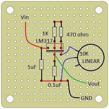
I have an adustable wall wart that is 3v - 6v - 9v - 12v so I guess I could just use that on the 9V setting plugged into my DIM wires for the time being. I would like to set up a more permanent dimmer with controls, however. After doing some google searching (It will be nice when RC gets their search function upgraded) I found this RC thread that talks about dimming a Meanwell ELN-60-48-D. In it (page 1) stugray and evilc66 get in a discussion about making a controller to reduce a 12V wall warts voltage to exactly 10V and then adjust it using a pot: http://www.reefcentral.com/forums/sh....php?t=1793374 Stugray advises using a master pot to lower the voltage down to 10V and then using a second pot to achieve dimming: Quote:
Quote:
In the same thread they also mention that the D and P Meanwells are almost identical and at least for testing purposes you can use a 0-10V signal produced by one of the above circuits on the PWM Meanwell like it was a D Meanwell. I would like to do that now just to see what the dimming effects look like before I try and build a microprocessor. Does all of this sound good?
__________________
^ Click on my username and 'Visit Taqpol's Home Page!" to view my 220 gallon custom Miracles tank! -Alex |
||
|
|
|
|
04/04/2010, 03:20 AM
|
#15 |
|
Registered Member
Join Date: May 2008
Location: Durham, NC
Posts: 2,205
|
I got a lot done today, but like all of these projects I did think i would get even farther.
Marked out the LED placement, I used roughly 1.75" between LEDs and 2" between rows:  Blue LEDs in place for a sense of scale:  I then drilled 1/8" holes through the heatsink on either side of where an LED will end up. This will allow me to pass wires through the heat sink and hide everything in the fins: 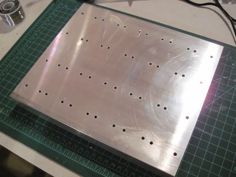 I also ground down some perpendicular channels so I can pass wires between the fins without going up and over:  Turtle Wax Polishing Compound was used to buff out any scratches and give a better surface for heat transfer. Right before I mounted the LEDs I also wiped down the surface with isopropanol and a lint free cloth:  RapidLed's kit came with Arctic Alumina Thermal compound so I used it. Like all two part epoxies you mix it in a 1:1 ratio on some kind of plastic sheet (I wax paper): 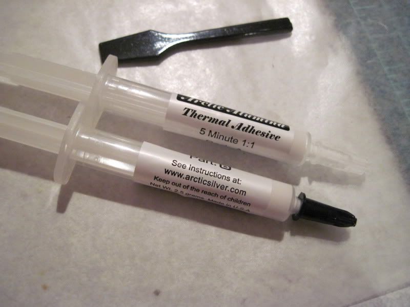 I then used the provided spatula to apply some mixed compound to the underside of the LED star, after I wiped it down with isopropanol and a lint free cloth: 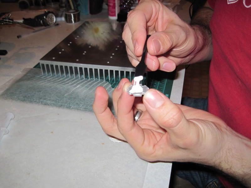 Press it into place on the heatsink. A slight twisting motion as you apply pressure really makes sure the thermal compound fills up all the imperfections:  I think I used a bit too much. One things for sure, these puppies are not coming off anytime soon:  Finished fixture: 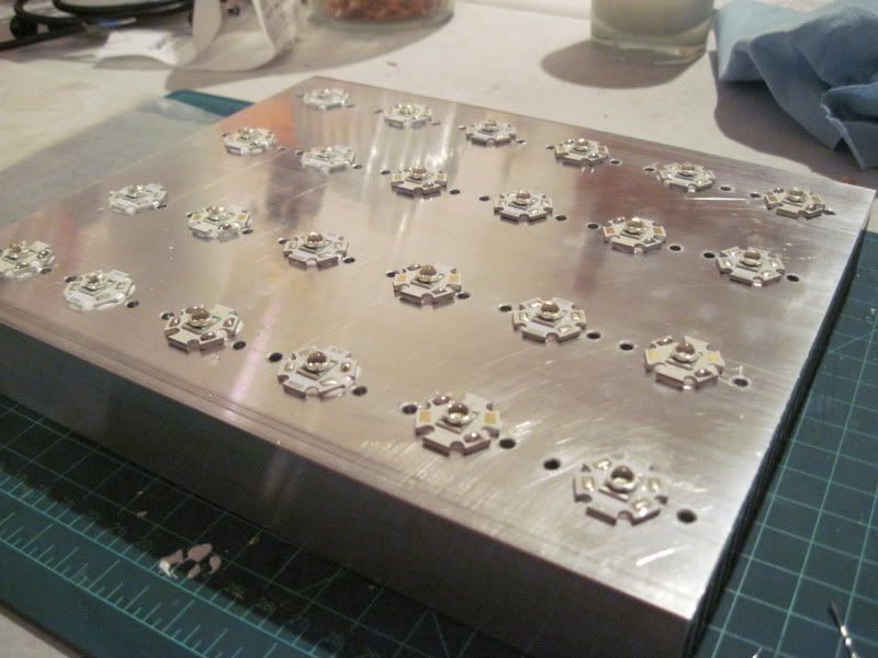
__________________
^ Click on my username and 'Visit Taqpol's Home Page!" to view my 220 gallon custom Miracles tank! -Alex |
|
|
|
|
04/04/2010, 03:40 AM
|
#16 |
|
Registered Member
Join Date: May 2008
Location: Durham, NC
Posts: 2,205
|
Also, following kcress's instructions (which I quoted on this page), soldering the XR-E cool whites which did not come pre-soldered was easy. I did these before I mounted them to the heat sink because I heard that the heat sink made it harder for the solder pads to heat up.
Touch the pre tinned soldering iron to the solder on one side of the pad:  Move the solder away and feed it in at a good clip until you get a nice mound:  I used a 30 watt soldering iron for everything I did today. I decided to use stugray's dimming circuit method as it did seem easier to me. Here was my proof of concept involving two 5Kohm pots and gator clips. While testing voltage across my second pot, I use the first pot to adust my maximum voltage. This is being fed by a 12v wall wart that was producing 12.1v on its own: 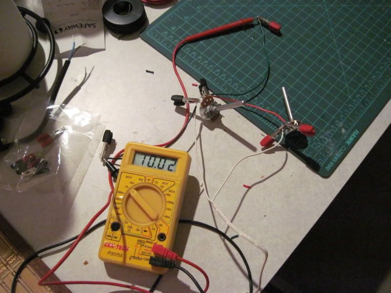 Then I wired it up so the multimeter would see what the meanwells dimming circuit sees. The wiring goes like this: Wall wart positive -> 1st pot high side 1st pot wiper -> 2nd pot high side 1st pot low side -> unconnected 2nd pot wiper -> Meanwell DIM+ (multimeter positive) 2nd pot low side -> wall wart negative Meanwell DIM- (multimeter negative) -> wall wart negative Note that the 2nd pots low side and the DIM- both connect to wall wart negative. Using this setup I was able to get any voltage from 10v to 0.0v:   Of course I wasn't content to leave it simple. I proceeded to make a circuit that would take my 12V wall wart and power a computer fan as well as the master pot and two 0-10v pots in parallel to control both of my Meanwells:   This board, along with my meanwells, will be mounted in a radio shack project box with the adjustable pots sticking through the case for use as an "external ballast". I do want to make sure of one thing before I continue, so someone with meanwell experience please let me know. In the thread I linked above they say the P and D meanwells are very similar and that you can dim a PWM meanwell with a 0-10V source just like what I have made. Is this true? I plan on using some kind of arduino based true PWM signal in the future but this seems much simpler for testing. If this will not work is there any way I can convert my 0-10V signal into a PWM signal?
__________________
^ Click on my username and 'Visit Taqpol's Home Page!" to view my 220 gallon custom Miracles tank! -Alex |
|
|
|
|
04/04/2010, 04:23 AM
|
#17 |
|
Registered Member
Join Date: Sep 2009
Posts: 86
|
I have used 2x ELN60-P.
Originally hooked up to a 9v battery. These last about a week before the voltage starts to sag. I do NOT recommend driving the P models with less than 9v. Take the effort to make the pwm circuit floating around. I did notice that my lights were dimmer after 1-2 weeks on battery, and recording less than 5v from my battery. So it does work, but never designed for it. I ended up buying a non dimming ELN60 model instead. You can also achieve 10v by using 3 diodes in series. 3x 0.6-0.7 = ~2v. You can easily get 10v from a 12v plug pack. To calibrate current, SVR2 is on the far right of the board. You can dial it down if your using XPE for Royal Blues. XPG can take full grunt otherwise. I suggest turning it off whilst adjusting. Final warning, if you look at datasheet, the output voltage is between 24-48v. You want to hook up enough leds in series, to take the min 24v. Otherwise risk magic smoke. I used a lab power supply to test my wiring, and put meanwells on last. --- You also want to do something about the rough edges on the Fins. The sharp edges can possibly cut the wire insulation over time. Need grommets ? Debur holes too. I would suggest going under the heatsink like everyone else does. I have drilled a hole through my heatsink, to tie a hoop. This takes strain off the wires. Meanwells live on a shelf. Also, good idea to run an earth to the heatsink itself. You dont want to get shocked if anything ever comes loose. -- Dont want to sound critical, just sharing my experience. |
|
|
|
|
04/04/2010, 08:36 AM
|
#18 |
|
Premium Member
Join Date: Jan 2002
Location: O'Fallon, IL
Posts: 4,520
|
Lookin good...
|
|
|
|
|
04/04/2010, 08:54 AM
|
#19 |
|
Registered Member
Join Date: Oct 2008
Location: Huntsville, AL
Posts: 2,736
|
Thanks for posting. I can't get enough of these LED threads. I am still a couple years out on a major move and tank upgrade, so after that, and after you guys work out all the kinks
 , I can start my own LED build. , I can start my own LED build.Looking good |
|
|
|
|
04/04/2010, 04:11 PM
|
#20 |
|
Registered Member
Join Date: May 2008
Location: Durham, NC
Posts: 2,205
|
This is coming along really fast! I forgot how much I enjoy soldering and electricity stuff.
ALL of the blue LEDs wired in series!  Wiring hidden in the fins:  With all that done and my voltage regulator working, its time to wire up some drivers! Standard AC power chord, soldered and heat shrink'ed with a lighter: 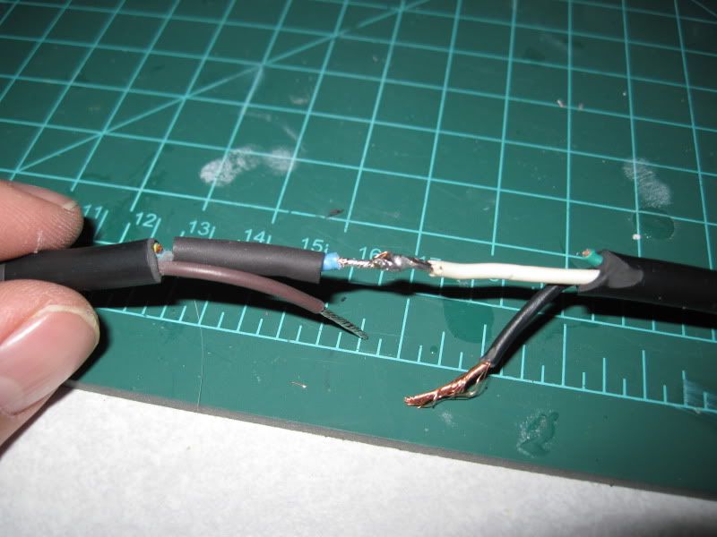  Hooked everything up with aligator clips. With no LEDs the driver was producing almost exactly 48V! 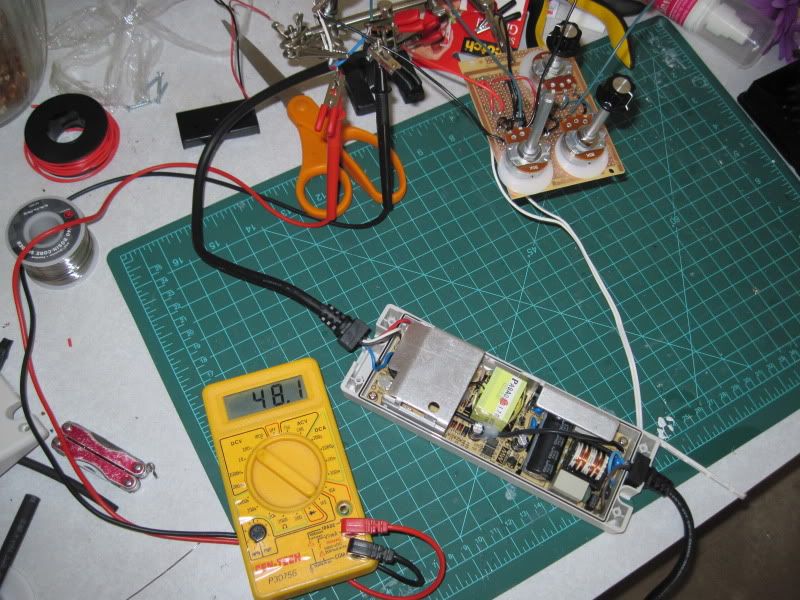
__________________
^ Click on my username and 'Visit Taqpol's Home Page!" to view my 220 gallon custom Miracles tank! -Alex |
|
|
|
|
04/04/2010, 04:19 PM
|
#21 |
|
Registered Member
Join Date: May 2008
Location: Durham, NC
Posts: 2,205
|
As suggested I hooked my multimeter up in series with the LEDs after turning the SVR2 pot down all the way (counter-clockwise). It turns out my multimeter does work just fine after I switched the positive chord to the 10A socket.
 Lights! with my dimming circuit on full blast (10V) and the SVR2 pot all the way down the rig only drew 0.15A yet I was still seeing spots. 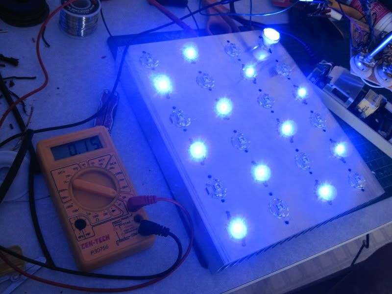 Adjusted the SVR2 pot until my amp meter read 0.7A, this level is almost blinding without optics! 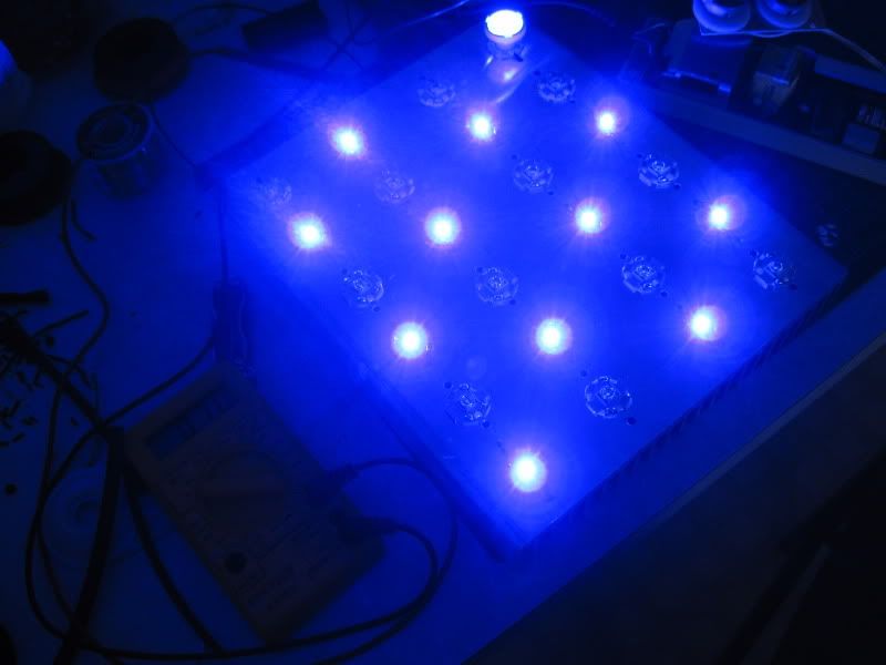 The lowest I can go with my dimming circuit pot is 0.09A, it will shut off after this.  60 degree optics, fully dimmed.  60 degree optics, full power.  The ceiling above me. I am really impressed by the spread of 60 degree optics. 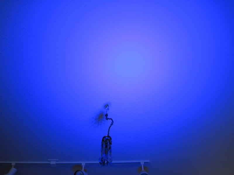 So my question now is why is 700mA the max, I thought these LEDs were rated all the way up to 1A. I don't think I would (or need) to go that high, but if I'm looking for a little more PAR down the road would it hurt to go up to maybe 800-850 mA saying that I have enough cooling?
__________________
^ Click on my username and 'Visit Taqpol's Home Page!" to view my 220 gallon custom Miracles tank! -Alex |
|
|
|
|
04/04/2010, 05:11 PM
|
#22 |
|
Registered Member
Join Date: Aug 2008
Location: Barrie, Ontario, Canada
Posts: 1,934
|
Alex,
Thats awesome. Could you list out all the products and where to get them for people that might want to follow in your footsteps. Any chance you could test the PAR at different distances under water. I am looking to upgrade and i may want to give LEDs a chance. Do you ever need to replace the bulbs? |
|
|
|
|
04/04/2010, 05:54 PM
|
#23 |
|
Premium Member
Join Date: May 2004
Location: Duluth, Mn
Posts: 1,508
|
I was suprised how quickly things move when you get going. Nice job. Next one I do, I'll conceal the wires.
|
|
|
|
|
04/04/2010, 06:45 PM
|
#24 |
|
Registered Member
Join Date: Nov 2009
Location: sioux city
Posts: 401
|
wow great job... almost looks ready to hang on the tank... i cant wait to see... i just ordered my leds and a heat sink... next payday hopefully i can buy my drivers... im really excited. looks good tho.
|
|
|
|
|
04/04/2010, 07:34 PM
|
#25 |
|
Team RC Member
Join Date: Jul 2005
Location: houstonia
Posts: 7,989
|
great project. any plans with the finished product? Or is it really just a test rig?
__________________
-Chris- You don't win friends with salad. "Look! They're trying to learn for free!" ... "Use your phony guns as clubs!" Current Tank Info: rectangluar? wet? |
|
|
|
|
|
|